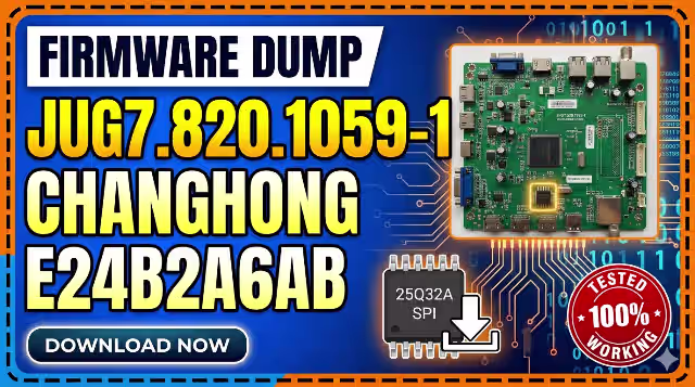
JUG7.820.1059-1 Firmware Dump
CHANGHONG E24B2A6AB TV
Main Board Firmware • SPI Flash Dump • Tested & Verified
Firmware Specifications
Complete SPI flash firmware dump for the CHANGHONG E24B2A6AB LED television, extracted from the JUG7.820.1059-1 main board. This dump has been read, verified, and tested for a full restore using the RT809H universal programmer. Confirmed 100% working on the original hardware configuration.
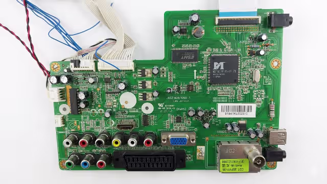
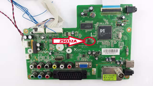
SPI Flash Chip Location
The 25Q32A SPI flash memory IC is located on the main board as indicated below. Use the RT809H programmer with an SOP8 clip or desolder the chip for direct socket programming.
Common Issues & Symptoms
The following problems on the CHANGHONG E24B2A6AB with the JUG7.820.1059-1 main board can typically be resolved by re-flashing the SPI firmware dump:
Diagnostic & Repair Protocol
Before flashing the firmware, follow this systematic diagnostic protocol to confirm the SPI flash is the root cause of the failure:
🔌 Step 1 – Power Supply Verification
- Measure standby voltage output: expected 5V STB on power supply connector
- Verify main voltage rails: 12V and 24V under load condition
- Check for swollen or leaking electrolytic capacitors on the power board
- Confirm power supply responds to PS_ON signal from the main board
📺 Step 2 – Backlight Circuit Check
- Measure LED backlight driver output voltage at connector
- Test individual LED strips for open-circuit failures using a constant current source
- Verify backlight enable (BL_ON) signal from the main board T-CON interface
🔍 Step 3 – Main Board Visual Inspection
- Inspect for burnt components, cold solder joints, or physical damage near the SoC and SPI flash areas
- Check crystal oscillator continuity (typically 24 MHz or 27 MHz)
- Verify all ribbon cable and FFC connections are properly seated
- Test EEPROM and SPI flash supply voltage: expected 3.3V at VCC pin
💾 Step 4 – SPI Flash Verification
- Connect RT809H programmer to 25Q32A using SOP8 test clip or desolder for socket programming
- Read existing firmware – if read fails or returns all 0xFF or 0x00, the flash chip or data is corrupted
- Compare read data checksum with known good dump before concluding firmware corruption
- If chip is physically damaged, replace with new 25Q32A or compatible W25Q32
✅ Step 5 – Post-Flash Verification
- After writing, perform a Verify operation in RT809H software to confirm data integrity
- Reinstall or reconnect the SPI chip, reassemble all cables
- Power on and observe: boot logo should appear within 3–5 seconds
- Perform factory reset from service menu if OSD appears garbled
- Run auto channel scan and test all input sources (HDMI, AV, USB)
Programming Instructions (RT809H)
- Power off the TV and disconnect it from mains power completely. Wait 30 seconds for capacitors to discharge.
- Locate the 25Q32A SPI flash chip on the JUG7.820.1059-1 main board using the reference image above.
- Connect the RT809H programmer to the chip using an SOP8 test clip. Ensure correct pin 1 orientation. Alternatively, desolder the chip and place it in the SOP8 socket on the programmer.
- Open the RT809H software on your PC. Select chip model: W25Q32 / 25Q32A (Winbond compatible). Set interface to SPI.
- Read the existing firmware first and save it as a backup file. Verify the read operation completes without errors.
- Erase the chip completely using the “Erase” function. Wait for confirmation that erase is complete.
- Load the downloaded firmware file into the RT809H software buffer. Click “Write” to program the firmware to the 25Q32A chip.
- Verify the write by clicking “Verify” – the software should report 0 errors and a matching checksum.
- Disconnect the programmer, resolder the chip if desoldered, and reassemble the TV. Reconnect all cables and LVDS ribbon.
- Power on the TV and verify normal boot, OSD operation, all inputs, sound output, and channel tuning functionality.
Video Guide
Watch the complete firmware dump and flashing tutorial for this model:
Download Firmware
Click the button: first click opens a sponsor page in a new tab, second click redirects to the download page.