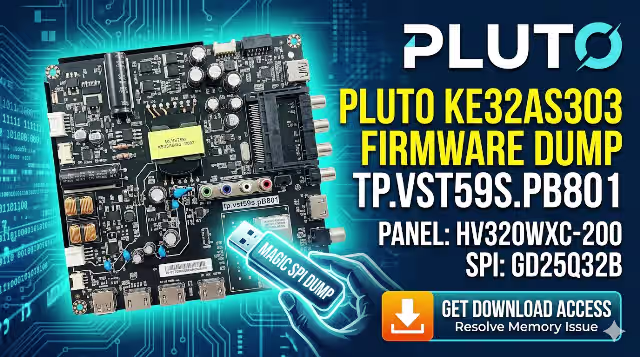
TP.VST59S.PB801 Firmware Dump
PLUTO KE32AS303 TV
GD25Q32B SPI Flash Memory Fix — 100% Tested & Working
Firmware Dump Overview
This page provides a fully tested and verified SPI memory dump for the TP.VST59S.PB801 main board installed in the PLUTO KE32AS303 television. The dump targets the GD25Q32B flash memory IC and resolves all common memory-related failures, including boot loops, no-start conditions, and corrupted EEPROM data. The firmware has been programmed and validated using the RT809H universal programmer.
This resource is intended exclusively for qualified television repair technicians who possess the necessary tools and experience to perform SPI-level board repair safely.
Hardware Specifications
| Brand | PLUTO |
|---|---|
| Model | KE32AS303 |
| Main Board | TP.VST59S.PB801 |
| LCD Panel | HV320WXC-200 |
| Panel Resolution | 1366 x 768 (HD Ready) |
| SPI Flash IC | GD25Q32B |
| Flash Capacity | 32 Mbit (4 MB) |
| Programmer Method | RT809H Universal Programmer |
| Firmware Status | 100% Tested & Working |
| Dump Type | Full SPI Bin (Read/Write) |
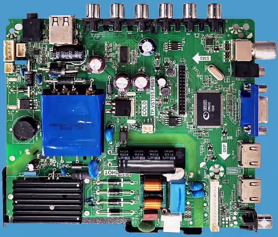
SPI Flash Chip Location
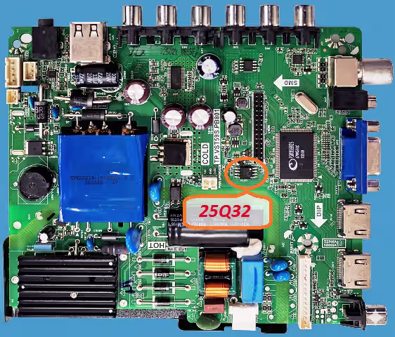
The GD25Q32B SPI flash IC is located near the main processor on the TP.VST59S.PB801 board. The chip is a standard 8-pin SOP package. Identify pin 1 by the dot marking on the IC before connecting to the RT809H programmer clip or socket adapter.
Common Issues — PLUTO KE32AS303
The following symptoms indicate SPI memory corruption or failure on this model. If the TV exhibits any of these problems, a firmware dump reflash is the recommended repair path:
- TV stuck on logo screen with endless boot loop
- Dead set condition — standby LED on but no power-up response
- TV powers on then shuts off immediately after 2–3 seconds
- Main board not responding to remote or panel buttons
- Distorted OSD menu or missing on-screen graphics
- Audio present but no video output (black screen with sound)
- Channel data and factory settings lost after every power cycle
- Firmware update failed — unit now bricked via USB method
- Backlight turns on briefly then goes dark with relay click
- HDMI and AV inputs not detected or locked out
Diagnostic & Repair Protocol
Follow this step-by-step protocol to diagnose the fault, extract the failed firmware, and write the new SPI dump to restore full functionality:
- Visual Inspection: Unplug the TV completely. Open the back cover and inspect the TP.VST59S.PB801 board for burnt components, swollen capacitors, or cold solder joints around the power regulator section and SPI IC area.
- Verify Power Rails: Using a multimeter, confirm that the main board receives the correct 5V and 3.3V supply rails from the power board. The GD25Q32B requires stable 3.3V VCC to operate. Low voltage can cause data corruption.
- Identify the SPI Chip: Locate the GD25Q32B 8-pin SOP flash IC on the board. Confirm the marking reads GD25Q32B or 25Q32. Note the pin 1 orientation dot before proceeding.
- Connect the RT809H Programmer: Use the SOP8 test clip or desolder the chip. Connect to the RT809H programmer. Launch the RT809H software and select the correct IC model: GD25Q32B (or compatible GD25Q32).
- Backup the Original Dump: Before writing, always read the existing flash content and save it as a backup file. This preserves the original data in case of any issues during the repair process.
- Erase the Flash Chip: Perform a full chip erase to clear all corrupted data sectors. Verify that the erase operation completes without errors in the programmer software.
- Write the New Firmware Dump: Load the downloaded TP.VST59S.PB801 SPI bin file into the RT809H software. Execute the write operation. Wait for it to complete without interruption.
- Verify the Written Data: Use the verify function in RT809H to compare the written data against the source file. The verification must show a 100% match with zero byte errors.
- Reinstall and Test: Resolder the chip if it was removed, or disconnect the test clip. Reassemble the TV and power it on. The TV should boot to the factory default state with full OSD functionality.
- Post-Flash Configuration: Enter the service menu to configure panel settings, region, and tuner parameters if needed. Run auto-scan for channels and verify all inputs (HDMI, AV, USB) function correctly.
Video Tutorial
Watch the complete firmware dump and flashing procedure for the TP.VST59S.PB801 main board. This tutorial covers chip identification, RT809H setup, and the full write-verify process:
Download Firmware Dump
TP.VST59S.PB801 — SPI Dump File
PLUTO KE32AS303 | GD25Q32B | 4 MB Bin File | RT809H Ready
Step 2 — Download SPI DumpClick Step 1 first to unlock, then click Step 2 to download the file