This professional firmware dump is exclusively prepared for qualified television repair technicians. The TP.S512.PB83 SPI flash memory dump provides a complete, verified solution for restoring the FUEGO 32VT3710HDT2 television to full factory-operational status. This binary image has been extracted, validated, and confirmed 100% working on the exact hardware configuration detailed below.
Hardware Specifications
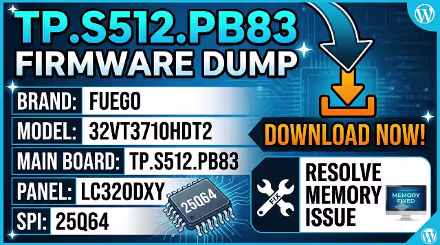
| Brand | FUEGO |
|---|---|
| Model | 32VT3710HDT2 |
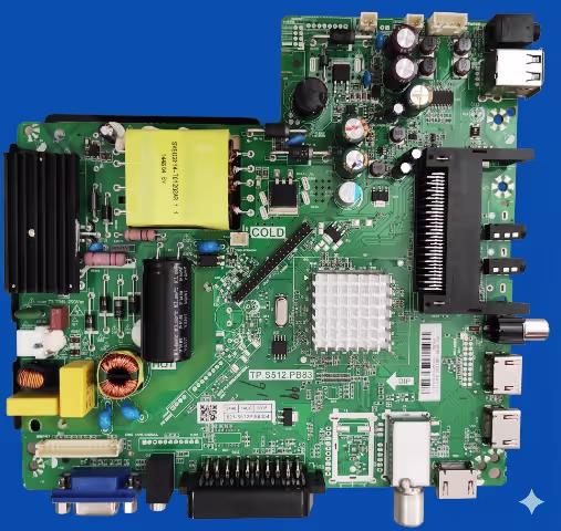
| Main Board | TP.S512.PB83 |
| Display Panel | LC320DXY |
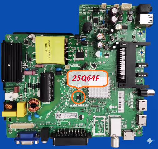
| SPI Flash IC | 25Q64 (64Mbit / 8MB) |
| Programmer | RT809H Universal Programmer |
| Firmware Status | Tested 100% Working |
| File Type | Binary Dump (.bin) |
Common Issues Resolved by This Firmware
The following symptoms on the FUEGO 32VT3710HDT2 are directly associated with corrupted or degraded SPI flash memory content on the TP.S512.PB83 board. This dump resolves all listed issues:
Diagnostic & Repair Protocol
Follow this step-by-step procedure to diagnose, flash, and verify the firmware on the TP.S512.PB83 main board. Each step is critical for a successful repair outcome.
Phase 1: Pre-Repair Diagnostics
- Visual Inspection: Examine the TP.S512.PB83 board for physical damage including burnt components, swollen capacitors, cracked solder joints, and corrosion near the power input section and SPI flash IC area.
- Power Supply Verification: Measure all output voltages from the PSU. Confirm 5V standby, 12V main, and 3.3V logic rails are within acceptable tolerance before proceeding with any firmware work.
- SPI IC Identification: Locate the 25Q64 SPI flash memory chip on the board. It is an 8-pin SOP8 package typically positioned near the main processor. Verify the IC marking reads “25Q64” (Winbond W25Q64 or equivalent).
Phase 2: Firmware Backup & Flash
- Connect RT809H Programmer: Attach the SOP8 test clip directly to the 25Q64 IC. If performing in-circuit programming, ensure the TV is completely disconnected from mains power. For off-board programming, desolder the SPI chip using hot air at 320°C with appropriate flux.
- Read & Backup Original Dump: Open the RT809H software, auto-detect the 25Q64 chip, and perform a full read. Save this original dump file as a backup. Perform two consecutive reads and compare checksums to verify read integrity.
- Erase SPI Flash: Execute a full chip erase command. Verify the erase operation completes successfully with the blank check function confirming all bytes are 0xFF.
- Write New Firmware: Load the downloaded TP.S512.PB83 firmware dump file into the RT809H software. Execute the write/program command. The 8MB file will take approximately 60-90 seconds to flash.
- Verify Written Data: After writing, perform a verify operation to compare the chip contents against the source file. The verification must show a 100% match with zero errors.
Phase 3: Post-Flash Validation
- Reassemble & Power Test: Disconnect the programmer, reassemble all connections, and apply power. The TV should boot to the home screen or channel display within 8-15 seconds. If using a desoldered chip, resolder with proper alignment and reflow.
- Functional Verification: Test all inputs (HDMI, AV, USB, antenna), verify OSD menu navigation, confirm remote control response, run auto channel scan for DVB-T2, and check audio output on all sources.
- Burn-in Test: Allow the TV to operate for a minimum of 2 hours continuously to ensure thermal stability and confirm no intermittent failures occur under sustained operation.
Video Tutorial
Watch the complete firmware dump and flashing procedure for the TP.S512.PB83 main board. This tutorial covers the full diagnostic, programming, and verification workflow.
Download Firmware Dump
TP.S512.PB83 — FUEGO 32VT3710HDT2 — SPI 25Q64 — Binary Dump File (8MB)
Step 1: A sponsor page opens in a new tab. Step 2: Click again to access the direct firmware download link.