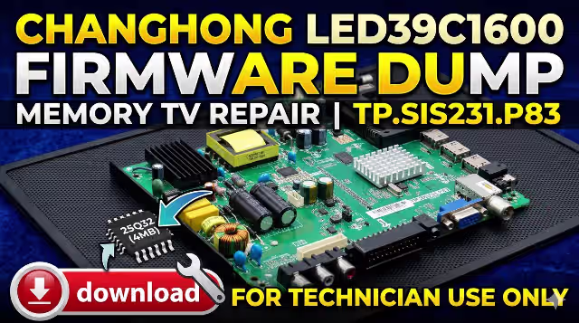
TP.SIS231.P83 Firmware Dump
CHANGHONG LED39C1600 Memory Repair
Verified full SPI flash dump for dead-set recovery and memory IC replacement. RT809H programmer method — tested and confirmed 100% working.
About This Firmware Dump
This technical resource provides a complete SPI flash memory dump extracted from a known-good CHANGHONG LED39C1600 television equipped with the TP.SIS231.P83 universal main board. The dump was created specifically to assist repair technicians dealing with memory corruption, boot failure, and dead-set conditions on this model.
The firmware binary includes all operating system data, bootloader configuration, panel timing parameters for the M390F13-E2-A LCD panel, channel tuning defaults, and factory calibration settings. It is designed to be flashed directly onto a 25Q32 SPI flash IC using the RT809H universal programmer, restoring full TV functionality without additional software configuration.
This file has been verified through multiple successful repairs across different production batches of the LED39C1600. After flashing, all TV functions — including display output, audio processing, OSD navigation, input switching, and remote control — operate as expected from factory state.
Hardware & Firmware Specifications
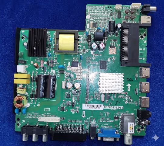
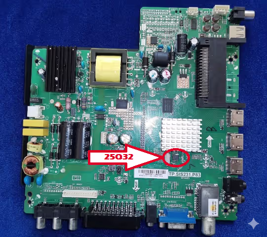
SPI Flash IC Location on Board
The image below identifies the exact position of the 25Q32 SPI flash memory IC on the TP.SIS231.P83 main board. This is the target chip for reading, erasing, and programming the firmware dump.
Known Issues & Failure Symptoms
The following documented symptoms indicate SPI flash memory corruption or failure on the TP.SIS231.P83 board in the CHANGHONG LED39C1600. All listed issues have been confirmed resolvable by reflashing the firmware dump provided on this page.
TV shows no signs of life. The standby indicator remains off despite confirmed working power supply (5VSB present at main board connector). The SPI flash boot sector is corrupted, preventing the main SoC from initializing.
Red standby LED illuminates but TV does not respond to power button or remote control. The processor cannot load the startup routine from corrupted memory, keeping the system in a permanent standby state.
TV powers on, shows the CHANGHONG splash screen briefly, then shuts down and restarts automatically. This continuous loop indicates a checksum failure in the firmware during the boot verification process.
The manufacturer logo appears and remains frozen on screen indefinitely. The TV never progresses to the input source or live TV display. The main application firmware block is corrupted beyond the bootloader stage.
Panel backlight turns on (screen glows), but no image, OSD menu, or any visual output appears. The LVDS initialization data or panel timing configuration within the flash memory is damaged or missing.
Screen shows scrambled colors, horizontal/vertical lines, mirrored image, or incorrect resolution. Panel configuration parameters (M390F13-E2-A timing tables) in the firmware are corrupted.
Picture displays normally but no sound from internal speakers, headphone jack, or HDMI ARC. The audio codec initialization sequence and volume control parameters are stored in the flash and have become corrupted.
On-screen display shows garbled text, incorrect language that cannot be changed, or freezes completely when accessing settings. Menu framework and localization data in the SPI flash is damaged.
Neither the IR remote nor the physical button board on the TV chassis produces any response. Hardware is confirmed working but the key-mapping and IR protocol data in firmware is corrupted.
All external input sources show “No Signal” despite functional connected devices. The input switching logic, HDMI handshake routines, and source detection firmware are stored in flash memory.
TV turns on momentarily then shuts down within 3–10 seconds. The watchdog timer in the main SoC detects firmware read errors and triggers a protective shutdown to prevent hardware damage.
An interrupted or incorrect USB firmware update has left the TV in an unrecoverable “bricked” state. The partially written flash data must be erased and replaced with a complete working dump via direct SPI programming.
Diagnostic & Repair Protocol
Follow this systematic repair workflow to diagnose memory-related failures and reflash the TP.SIS231.P83 board. Ensure the power supply and backlight driver boards have been verified as functional before beginning this protocol.
Pre-Repair Safety & Inspection
- Disconnect the TV from AC mains power completely.
- Wait a minimum of 2 minutes for all capacitors on the power supply board to discharge fully — measure with a multimeter to confirm 0V on main filter caps.
- Remove the rear cover screws and carefully detach the back panel.
- Perform a thorough visual inspection of the TP.SIS231.P83 main board: check for burnt components, swollen electrolytic capacitors, cracked solder joints, moisture corrosion, or physical impact damage.
- Verify all cable connections: LVDS ribbon to panel, speaker wires, IR sensor board, physical button board, and power supply harness.
- Wear an ESD wrist strap grounded to the TV chassis throughout the entire procedure.
Power Supply Output Verification
- Reconnect AC power temporarily with the main board disconnected from the power supply.
- Measure standby voltage: 5V ±0.25V should be present on the power supply output connector.
- Reconnect the main board, power on, and measure the main operating voltage: 12V ±0.5V should activate when the SoC sends the power-on control signal.
- If 5V standby is present but no 12V rail activates, and the power supply is confirmed good with a dummy load, the main board SoC is not sending the power-on signal — this confirms firmware / memory failure.
- Disconnect AC power again before proceeding to the next step.
SPI Flash IC Identification & Access
- Locate the 25Q32 SPI flash IC on the main board using the reference image provided above.
- Confirm the IC package type: SOP8 (8-pin small outline package). Common markings include W25Q32, EN25Q32, GD25Q32, or MX25L3206E.
- Note the pin 1 orientation marker (small dot or notch on the IC) — this is critical for correct reinstallation.
- Choose your access method: Method A — Desolder the IC using a hot-air rework station (recommended for failed/replacement ICs). Method B — Attach a SOIC8 test clip for in-circuit read/write (faster, non-destructive, but requires all power disconnected).
Desoldering the Flash IC (Method A)
- Apply generous flux paste around all 8 pins of the IC.
- Set hot-air station to 330–360°C, medium airflow, with a suitable nozzle diameter.
- Heat evenly around the IC — do not concentrate on one side. Use tweezers to gently lift the IC once all pins are free (typically 20–40 seconds).
- Clean the PCB pads with solder wick and isopropyl alcohol (IPA). Inspect for lifted pads or damaged traces.
- If the original IC is suspected as physically failed (read errors, inconsistent data), use a new blank 25Q32 IC.
Reading & Backing Up Original Data
- Place the desoldered IC into the RT809H programmer using the SOP8 to DIP8 adapter socket. Ensure pin 1 alignment.
- Launch RT809H programmer software on your PC.
- Select the correct IC model from the database: W25Q32 / EN25Q32 / GD25Q32 (depending on your chip marking).
- Click “Read” to dump the existing flash contents.
- Save this backup file with a descriptive name (e.g.,
LED39C1600_original_backup.bin). Even if corrupted, this backup may contain recoverable EEPROM or channel data.
Erasing & Programming the Firmware
- With the IC still in the programmer socket, click “Erase” to perform a full chip erase. Wait for the “Erase OK” confirmation.
- Click “Blank Check” to verify the IC is completely empty (all bytes 0xFF). If blank check fails, the IC may be defective — replace with a new 25Q32.
- Click “Open File” and navigate to the downloaded TP.SIS231.P83 firmware dump file.
- Click “Program” (or “Write”) to flash the firmware onto the IC. The progress bar should complete without errors.
- Immediately after programming, click “Verify” to compare the written data against the source file. The result must show “Verify OK — 100% Match”.
- If verification fails on the first attempt, erase and reprogram. If it fails again, the IC is defective and must be replaced.
Reinstallation, Assembly & Testing
- Resolder the programmed 25Q32 IC back to the main board. Apply flux, align pin 1 carefully, and use either hot-air or a fine-tip soldering iron.
- Inspect all 8 solder joints under magnification (loupe or microscope). Ensure no solder bridges between pins, no cold joints, and no lifted PCB pads.
- Reconnect all internal cables: LVDS panel ribbon, speaker connectors, IR sensor board, button board, and power supply harness.
- Double-check all connections, then plug in AC power and turn on the TV.
- First boot may take 30–60 seconds as the system initializes from fresh firmware. Do not power off during this time.
- Perform the following functional tests: ✓ Display output and picture quality on all inputs (TV tuner, HDMI, AV, USB) ✓ OSD menu navigation in all submenus ✓ Audio output from speakers and headphone jack ✓ Remote control response for all buttons ✓ Physical button board operation ✓ Channel auto-scan with antenna connected ✓ Power off/on cycling (3–5 times) to confirm stability
- If all tests pass, reassemble the TV rear cover and return to service.
- This firmware dump is strictly model-specific for CHANGHONG LED39C1600 with panel M390F13-E2-A. Using it on a different TV model, board revision, or panel type can cause permanent hardware damage.
- Always back up the original flash contents before erasing, even if the data appears corrupted.
- Ensure the 25Q32 IC is the correct capacity (4MB / 32Mbit). Programming a wrong-size dump to a different capacity IC will not work.
- Work in an ESD-safe environment with proper grounding at all times. Static discharge can destroy the SPI flash IC and main board SoC.
- TV main boards contain high-voltage capacitors even when unplugged. Always verify discharge before touching any components.
- This resource is intended for professional electronics repair technicians only. Improper use may result in equipment damage, electrical shock, or fire hazard.
Video Guide — RT809H Flash Programming
Watch the complete programming tutorial demonstrating the SPI flash read, erase, write, and verify process using the RT809H universal programmer.
Download Firmware Dump
TP.SIS231.P83 — CHANGHONG LED39C1600
Flash IC: 25Q32 · Size: 4 MB · Programmer: RT809H
Verified 100% Working
Two-step download: First click opens a sponsor page in a new tab. Then click again to access the direct download link. Disable ad-blockers if needed.
Share With Fellow Technicians
Frequently Asked Questions
What SPI flash IC does the TP.SIS231.P83 board use?
The TP.SIS231.P83 main board uses a 25Q32 SPI NOR flash memory IC with 4MB (32 Mbit) capacity in an SOP8 package. Common manufacturer variants include Winbond W25Q32, EON EN25Q32, GigaDevice GD25Q32, and Macronix MX25L3206E — all are compatible.
Which programmer do I need to flash this firmware?
The RT809H universal programmer is recommended with an SOP8 adapter socket. Alternatively, you can use a SOIC8 test clip for in-circuit programming without desoldering. Other compatible programmers include the RT809F, CH341A, and EZP2023+, though the RT809H provides the most reliable results.
Can I use this firmware on other TV models or different panels?
No. This dump is specifically calibrated for the CHANGHONG LED39C1600 with the M390F13-E2-A panel. Using it on a different TV model, board revision, or panel type will result in incorrect panel timing, resolution mismatch, or complete failure to boot. It may also permanently damage the panel or main board.
What if the verify step fails after programming?
A verification failure usually indicates a defective flash IC. Erase and reprogram once more. If verification fails again, replace the 25Q32 IC with a new blank chip and repeat the programming procedure. Also check for poor contact in the programmer socket or adapter.
Do I need to configure anything after flashing?
The firmware includes factory-default settings, so the TV should boot directly to the initial setup screen. You will need to perform a channel auto-scan, set your preferred language, and adjust picture/audio settings. No additional software or USB update is required.