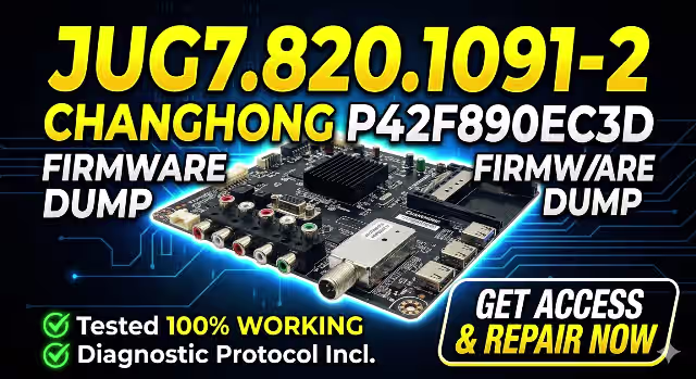
JUG7.820.1091-2 Firmware Dump – CHANGHONG P42F890EC3D Free Download
📋 Firmware Specifications
| TV Brand / Model | CHANGHONG P42F890EC3D |
| Main Board | JUG7.820.1091-2 |
| Panel | PM42H3000 |
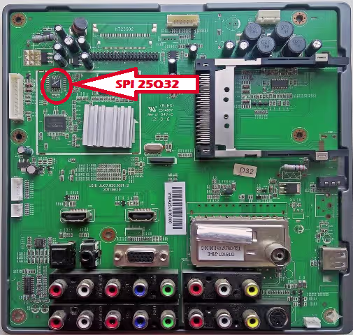
| SPI Flash IC | FL032KIF (S25FL032K) — 32 Mbit |
| Programmer | RT809H Universal Programmer |
| File Type | Full Memory Dump (.bin) |
| Firmware Status | ✅ Tested 100% Working |
📝 About This Firmware Dump
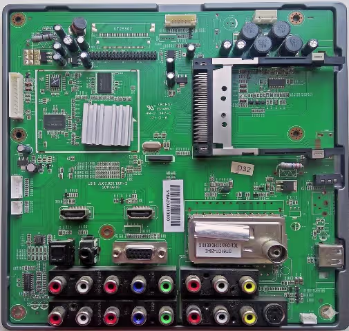
This is a full SPI memory dump extracted from a known-good CHANGHONG P42F890EC3D television equipped with the JUG7.820.1091-2 main board. The dump was read from the FL032KIF (S25FL032K) 32 Mbit SPI flash chip using an RT809H universal programmer.
This firmware file contains the complete flash memory content including bootloader, main application, EEPROM data, and channel configuration. It is intended for professional TV repair technicians who need to restore a corrupted or dead main board to factory working condition.
The file has been verified and tested — after flashing, the TV boots normally, all inputs function correctly, and the on-screen menu operates without errors.
🔧 Common Issues & Symptoms (CHANGHONG P42F890EC3D)
The following faults on the CHANGHONG P42F890EC3D with JUG7.820.1091-2 board are typically caused by SPI flash corruption and can be resolved by flashing this firmware dump:
Important: Before flashing firmware, always verify that the power supply board and T-CON board are functioning correctly. A firmware reflash will only resolve software/corruption-related issues.
🔬 Diagnostic & Repair Protocol
Phase 1 — Initial Hardware Inspection
Phase 2 — SPI Flash Memory Repair
Phase 3 — Reassembly & Final Testing
🎬 Video Tutorial — Flashing Guide
⬇ Download Firmware Dump
JUG7.820.1091-2 — CHANGHONG P42F890EC3D — FL032KIF (S25FL032K) — Full Dump
File format: .bin | Programmer: RT809H | Chip: S25FL032K (4MB)
❓ Frequently Asked Questions
What SPI flash chip does the CHANGHONG P42F890EC3D use?
The CHANGHONG P42F890EC3D with JUG7.820.1091-2 main board uses an FL032KIF (S25FL032K) 32 Mbit (4MB) SPI NOR flash chip in an SOP8 package.
Which programmer is recommended for flashing this firmware?
We recommend the RT809H universal programmer with an SOP8 adapter or test clip. The RT809H software will auto-detect the S25FL032K chip for seamless read/write operations.
Is this firmware dump tested and working?
Yes, this JUG7.820.1091-2 firmware dump has been tested 100% working on the CHANGHONG P42F890EC3D. After flashing, the TV boots normally with full functionality across all inputs and menus.
What common issues does this firmware fix?
This firmware resolves: dead/no power conditions, stuck on boot logo, boot loops, black screen with backlight, no signal on all inputs, EEPROM corruption, OSD menu failure, failed software updates, and remote control non-response — all caused by SPI flash data corruption.
Can I use a clip instead of desoldering the SPI chip?
In-circuit programming with a SOIC8 test clip is possible but may produce read/write errors due to interference from other components on the bus. For the most reliable results, desoldering the chip is recommended.
The TV still doesn’t work after flashing. What should I check?
If the firmware flash does not resolve the issue, verify: (1) PSU output voltages are correct, (2) no shorted components on the main board, (3) LVDS cable and panel are functional, (4) the correct firmware file was used, and (5) the SPI chip was soldered correctly with no bridged pins.