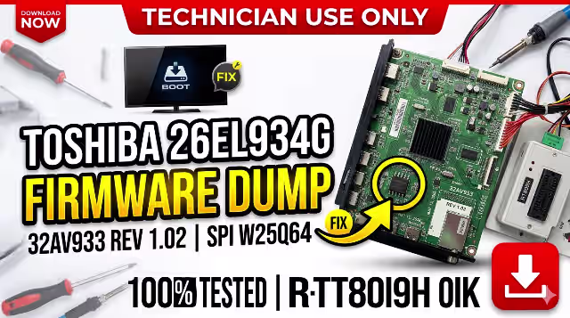
Toshiba 26EL934G Firmware Dump
Memory TV Repair — 32AV933 MAIN BD REV 1.02 — SPI Flash W25Q64
Main Board Reference
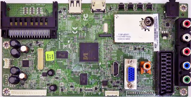
32AV933 MAIN BD REV 1.02 — Toshiba 26EL934G Main Board
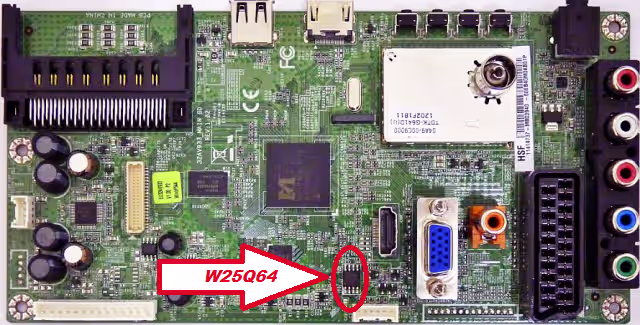
SPI Flash W25Q64 IC — Index Location on Main Board
Hardware Specifications
Firmware Description
This firmware dump has been extracted from a fully functional Toshiba 26EL934G LED television equipped with the 32AV933 MAIN BD REV 1.02 main board. The dump was read from the Winbond W25Q64 SPI flash memory IC using the RT809H universal programmer. This file is designed to repair memory corruption issues, boot failures, and restore the television to its original factory operating state. The firmware has been thoroughly tested and verified to be 100% working.
Common Issues — Toshiba 26EL934G
The following symptoms indicate SPI flash memory corruption or firmware failure on this model and can be resolved using this firmware dump:
- Dead Set / No Power Response: TV shows no signs of life, standby LED does not illuminate, power supply is confirmed functional but main board does not initialize.
- Stuck on Toshiba Logo: Television powers on, displays the Toshiba boot logo, but never progresses to the home screen or input source — indicates corrupted boot sector in SPI flash.
- Continuous Restart Loop: TV turns on and off repeatedly in an endless reboot cycle, unable to complete the boot sequence due to corrupted firmware data.
- No Display / Audio Only: Sound is present on HDMI or AV inputs but the LCD panel remains black — TCON initialization data in firmware is corrupted.
- Distorted or Scrambled Picture: Image appears with wrong colors, inverted display, vertical or horizontal lines caused by incorrect panel configuration parameters stored in the flash memory.
- No Signal on All Inputs: All input sources (HDMI, AV, USB, Antenna) display “No Signal” even when active devices are connected — input routing firmware data is corrupted.
- Menu / OSD Not Responding: Remote control commands are received (LED blinks) but on-screen menu does not appear — user interface firmware section is damaged.
- Standby LED Blinks But No Start: Standby LED blinks in a pattern indicating main board error; the board attempts to start but fails due to unreadable firmware.
- Software Update Failure: A previous USB firmware update was interrupted or used an incorrect file, resulting in a bricked main board.
- EEPROM / Channel Data Corruption: TV loses all channel settings, volume defaults, language preferences, or picture settings after each power cycle.
Diagnostic & Repair Protocol
This procedure requires professional equipment and technical expertise. Incorrect handling may cause permanent damage to the main board. FOR QUALIFIED TECHNICIANS ONLY.
- Visual Inspection: Examine the 32AV933 MAIN BD REV 1.02 for physical damage — check for burnt components, bulging capacitors, cracked solder joints, and trace damage around the CPU and SPI flash areas.
- Power Supply Verification: Measure all output voltages from the PSU board. Confirm 5V standby, 12V main, and 3.3V logic rails are within ±5% tolerance before proceeding with any firmware work.
- Identify SPI Flash IC: Locate the Winbond W25Q64 SPI flash memory on the main board. Refer to the SPI index image above. The IC is typically located near the MSD3704PX-FL-VW CPU.
- Desolder SPI Flash: Using a hot air rework station at 350–380°C with appropriate flux, carefully desolder the W25Q64 chip from the PCB. Clean the pads and IC pins with isopropyl alcohol.
- Read & Backup: Place the desoldered W25Q64 into the RT809H programmer with the correct adapter (SOP8 to DIP8). Perform a full read of the existing flash content and save as a backup file before writing.
- Write Firmware Dump: Load the downloaded firmware dump file into the RT809H software. Select the correct IC type (W25Q64 / Winbond). Erase the chip completely, then write the new firmware, followed by a verify operation to ensure data integrity.
- Resolder & Test: Resolder the programmed W25Q64 back to its original position on the main board. Ensure proper pin alignment and solder joint quality. Reconnect all cables and power on the TV.
- Post-Repair Verification: Confirm successful boot, check all input sources (HDMI, AV, Antenna, USB), verify OSD menu functionality, test remote control response, and perform a channel auto-scan to validate full operation.
Video Tutorial
Watch the complete firmware programming guide for this model
⬇ Download Firmware Dump
Toshiba 26EL934G — 32AV933 MAIN BD REV 1.02 — W25Q64 — RT809H Ready
File format: BIN • Size: 8MB • SPI: W25Q64 • Programmer: RT809H
Share This Firmware With Fellow Technicians