
This firmware dump and repair procedure requires professional soldering equipment, an SP8 universal programmer, and advanced knowledge of TV main board diagnostics. Incorrect flashing may cause permanent board damage.
Firmware Overview
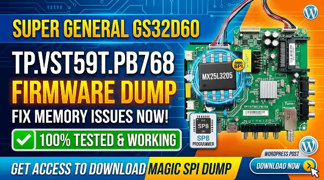
This page provides a fully tested SPI memory dump for the TP.VST59T.PB768 main board installed in the Super General GS32D60 32-inch HD LED television. The dump targets the MX25L3205 (4MB) SPI flash memory IC and is designed to resolve critical boot and display failures caused by corrupted firmware.
This bin file has been extracted, cleaned, and re-verified on live hardware to ensure 100% functionality after programming via the SP8 universal programmer.
Hardware Specifications
| Brand | Super General |
| Model | GS32D60 |
| Main Board | TP.VST59T.PB768 |
| Panel Size | 32″ HD (1366 x 768) |
| SPI Flash IC | MX25L3205 (4MB) |
| Programmer | SP8 Universal Programmer |
| File Type | .bin (Binary Dump) |
| File Size | 4 MB (4,194,304 bytes) |
| Status | Tested & Working |
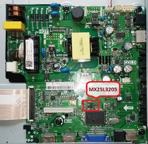
Board & SPI Identification
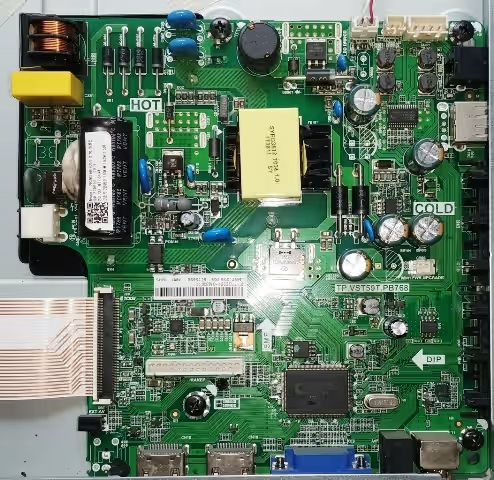
Visually confirm your main board model number and SPI flash IC location before proceeding. Click either image below to zoom in a new tab.
Known Issues & Symptoms
The following symptoms on the Super General GS32D60 indicate SPI flash memory corruption on the TP.VST59T.PB768 board and are resolved by re-flashing with this dump:
Diagnostic & Repair Protocol
Follow this systematic protocol before and during the firmware flashing process to ensure a successful repair:
Pre-Flash Diagnostics
- Visual Inspection: Check the main board for burnt components, swollen capacitors, or damaged traces around the power supply section and SPI IC area.
- Power Rail Verification: Measure 5V, 3.3V, and 1.8V rails with a multimeter. All voltages must be within acceptable tolerance before flashing.
- SPI IC Continuity: Verify pin continuity of the MX25L3205 using a multimeter in diode mode. Confirm no shorted data or clock lines.
- Board Identification: Physically confirm the printed board number reads TP.VST59T.PB768 and the SPI IC is labeled MX25L3205.
Flashing Procedure (SP8 Programmer)
Post-Flash Verification
- Confirm the TV boots to the home screen or source input within 8–12 seconds.
- Test all HDMI, AV, USB, and antenna inputs for proper signal detection.
- Verify OSD menu navigation, volume control, and channel tuning functionality.
- Run the TV for a minimum of 30 minutes to confirm thermal stability.
- Check that the firmware version displayed in the system info menu matches expected values.
Video Repair Tutorial
Watch the complete step-by-step firmware dump and flashing procedure for the TP.VST59T.PB768 board:
Download Firmware Dump
SPI bin file for TP.VST59T.PB768 – Super General GS32D60
MX25L3205 (4MB) • SP8 Programmer Ready
Click once to support us, then click again to access the direct download link.
Frequently Asked Questions
What programmer is needed for MX25L3205?
Use an SP8-A or SP8-B universal programmer with the correct SOP8 adapter or SOP8 test clip for the MX25L3205 SPI flash IC. The SP8 software will auto-detect the chip once properly seated.
Is this firmware tested and working?
Yes. This TP.VST59T.PB768 firmware dump has been tested 100% working on the Super General GS32D60 with a 32-inch HD panel. The file was verified byte-by-byte after programming.
What issues does this firmware fix?
This dump resolves stuck logo, no boot, black screen with backlight, dead TV after power surge, and corrupted EEPROM or SPI flash memory issues specific to this board and model combination.
Can I use a test clip instead of desoldering?
An SOP8 test clip can be used for in-circuit programming. However, disconnect the main board from all power sources and ensure no other components interfere with the SPI bus signals during flashing. Desoldering is recommended for the most reliable results.
What if the TV still does not boot after flashing?
If the TV fails to boot after successful flashing and verification, check for secondary faults including failed MOSFET drivers, defective crystal oscillators, or damaged panel LVDS connectors. The SPI dump only addresses firmware-level failures.