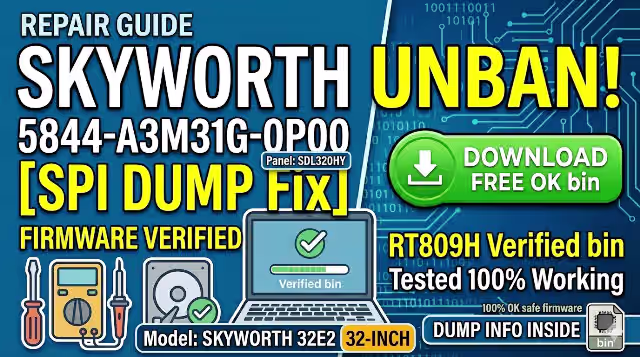
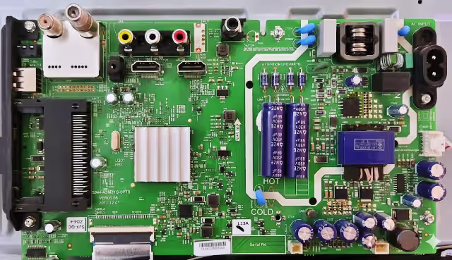
Access the 5844-A3M31G-0P00 firmware dump to resolve any memory-related issue on the SKYWORTH 32E2 LED TV. This is a verified SPI backup dump extracted directly from a fully working unit using the RT809H universal programmer. The firmware targets the 25Q64 SPI Flash chip mounted on this main board and has been tested 100% working — safe to flash for board-level repair.
Firmware Specifications
| TV Model | SKYWORTH 32E2 |
| Main Board | 5844-A3M31G-0P00 |
| LCD Panel | SDL320HY |
| SPI Flash IC | 25Q64 (Winbond W25Q64 — 8 MB) |
| Dump Type | Full SPI Backup Dump |
| Programmer | RT809H |
| File Status | ✅ Tested 100% Working |
Common Issues Resolved by This Firmware
The following symptoms on the SKYWORTH 32E2 (board 5844-A3M31G-0P00) typically indicate corrupted SPI Flash memory and can be fixed by re-programming the dump file:
- TV stuck on Skyworth logo — boot loop (no further loading)
- Power LED blinks but no picture and no backlight activation
- Dead set — no standby LED after confirming PSU voltages are normal
- TV turns on then shuts off immediately (protection mode)
- Distorted or scrambled OSD / menu after a power surge
- HDMI / AV / USB inputs not detected or not switching
- Software update failure — TV bricked during OTA or USB update
- Sound present but no image (panel-related settings corrupted in EEPROM area)
- Remote control unresponsive — IR commands not processed
- Automatic restart every few seconds — watchdog timer triggered by corrupt firmware
Diagnostic & Repair Protocol
Pre-Flash Diagnostics
- Visual Inspection: Examine the 5844-A3M31G-0P00 board for burnt components, swollen capacitors, or cold solder joints — especially around the power regulation section and SPI Flash IC area.
- Power Supply Verification: Confirm that the PSU delivers correct standby (5V) and main operating voltages (12V, 3.3V, 1.8V) before suspecting firmware corruption.
- Backlight Test: If the TV has no display, verify the LED backlight strips and driver circuit are functional. Use an external LED tester to confirm strip continuity.
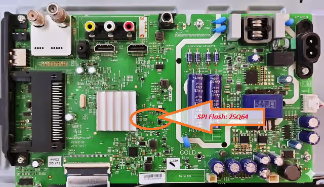
- SPI Flash Identification: Locate the 25Q64 chip on the main board (refer to image above). Confirm the IC marking matches — Winbond W25Q64 (8-pin SOIC package, 8 MB capacity).
Firmware Flashing Procedure
- Desolder the SPI Flash: Use a hot-air rework station (320°C–350°C) to carefully remove the 25Q64 chip from the board. Clean pads with flux and solder wick.
- Read Before Write: Place the chip on the RT809H programmer socket (or use an SOP8 clip for in-circuit reading). Read the existing firmware and save it as a backup — even if corrupted, keep it for reference.
- Erase the Chip: Perform a full chip erase through the RT809H software to clear all existing data.
- Write the Dump File: Load the downloaded 5844-A3M31G-0P00 firmware dump into the RT809H software. Select chip model W25Q64 and click Write / Program.
- Verify: After writing, use the Verify function to confirm the data matches the source file byte-for-byte. A successful verify ensures data integrity.
- Resolder the Chip: Re-mount the 25Q64 back onto the main board. Inspect solder joints under magnification to ensure no bridging.
- Power On Test: Reconnect the PSU and panel. Power on the TV — it should boot to the Skyworth home screen normally. Verify all inputs, OSD, and remote functions.
Warning: This firmware is strictly for the 5844-A3M31G-0P00 main board with SDL320HY panel. Flashing on a different board or panel combination may result in permanent damage. For technician use only.
Video Guide
Watch the full walkthrough for SPI Flash programming on this board:
Download Firmware Dump
File: 5844-A3M31G-0P00_SPI_25Q64_SKYWORTH_32E2.bin
Two-step verification required — click Step 1 first, then Step 2 will activate.
— Step 1: Verify Access —
Step 1 — Verify & Unlock
— Step 2: Download File —
Step 2 — Download Firmware
Tip: Always verify the chip ID in RT809H software before writing. Select WINBOND → W25Q64 from the IC list for correct read/write parameters.