 Tested and Verified
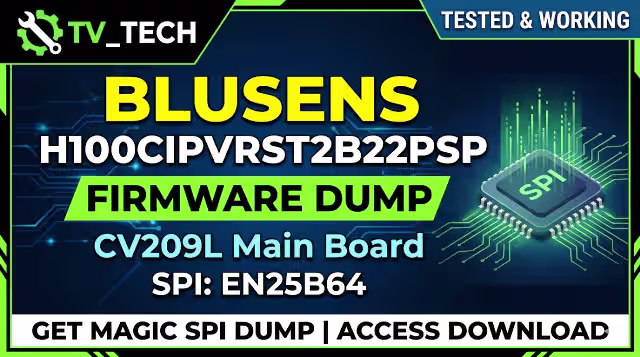
CV209L Firmware Dump – Blusens H100CIPVRST2B22PSP – SPI EN25B64 Download
This professional firmware dump resolves critical memory-related failures on the Blusens H100CIPVRST2B22PSP television equipped with the CV209L universal main board. The SPI bin file has been extracted from a fully functional unit, verified, and tested for reliability using the RT809H programmer. This resource is intended exclusively for qualified TV repair technicians.
Hardware Specifications
| Brand | Blusens |
|---|---|
| Model | H100CIPVRST2B22PSP |
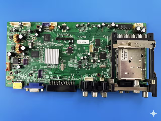
| Main Board | CV209L |
| Panel | LTM220M1-L01 (Samsung 22 inch) |
| SPI Flash Memory | EN25B64 (64Mbit / 8MB) |
| Programmer Method | RT809H Universal Programmer |
| File Type | BIN (Full Dump) |
| Status | Tested 100% Working |
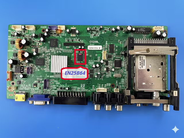
SPI Flash Memory Identification
Locate the EN25B64 SPI chip on the CV209L board near the main processor. The chip is an 8-pin SOP8 package manufactured by EON Silicon Solution. Confirm the part number printed on the chip surface matches before proceeding with the flash operation.
Common Issues and Symptoms
The following failure symptoms on the Blusens H100CIPVRST2B22PSP are typically caused by corrupted SPI firmware data and can be resolved by reflashing the EN25B64 memory chip with a verified dump:
- Dead set with no power indicator: The TV does not respond to the power button and the standby LED remains off despite correct power supply voltage on the main board.
- Boot loop or stuck on logo: The Blusens logo appears repeatedly or the television cycles between standby and power-on states without reaching the home screen.
- No display output with active backlight: The backlight activates but no image, OSD, or menu appears, indicating the main processor fails to initialize from corrupted firmware.
- No audio or distorted sound: Audio output is absent or garbled across all input sources due to corrupted audio codec initialization parameters in the SPI data.
- HDMI and AV input not detected: External devices connected via HDMI or AV are not recognized because the input selection firmware table is damaged.
- OSD menu freezing or partial display: The on-screen display loads incompletely, shows garbled characters, or freezes during navigation.
- Remote control unresponsive: The IR receiver functions at hardware level but commands are not processed due to corrupted key mapping data in memory.
- Automatic shutdown after a few seconds: The TV powers on briefly then shuts down as a protection response triggered by failed firmware integrity checks.
Diagnostic and Repair Protocol
Follow this systematic diagnostic procedure before flashing the firmware to ensure the issue originates from SPI memory corruption and not a hardware failure:
Phase 1 – Power Supply Verification
- Disconnect the TV from mains power and discharge all capacitors by waiting a minimum of 60 seconds.
- Measure the standby voltage output (typically 5V STB) from the power supply board using a digital multimeter.
- Verify all secondary voltage rails (12V, 5V, 3.3V) activate when the power-on command is sent via the front panel button.
- Inspect electrolytic capacitors on the power supply board for bulging, leaking, or reduced capacitance.
Phase 2 – Main Board Inspection
- Visually inspect the CV209L board for burnt components, cold solder joints, or damaged traces near the processor and SPI chip area.
- Verify the 3.3V supply rail at the EN25B64 VCC pin (pin 8) is stable and within tolerance.
- Check crystal oscillator operation using an oscilloscope to confirm clock signal presence at the main processor.
- Test the LVDS cable and connector for continuity if a panel-related failure is suspected before attributing the fault to firmware.
Phase 3 – SPI Firmware Flashing
- Desolder the EN25B64 chip from the CV209L board using a hot air rework station set to 350 degrees Celsius with moderate airflow to avoid damaging adjacent components.
- Place the chip in the SOP8 adapter socket of the RT809H programmer. Ensure correct orientation by aligning pin 1 with the socket marker.
- Open the RT809H software, select the chip model EN25B64 from the EON manufacturer list, and perform a full erase operation.
- Load the downloaded BIN file into the programmer software and execute the write operation. Wait for the process to complete without interruption.
- Perform a verify operation to confirm the written data matches the source bin file with zero byte errors.
- Resolder the EN25B64 chip back onto the CV209L board with proper flux application and solder paste. Inspect all 8 pins under magnification for bridges or cold joints.
- Reconnect all cables, apply power, and verify the TV boots normally to the home screen with full functionality including all inputs and OSD menus.
Video Repair Guide
Watch the complete step-by-step video tutorial demonstrating how to desolder, flash, and resolder the EN25B64 SPI chip on the CV209L main board using the RT809H programmer:
Download Firmware File
Blusens H100CIPVRST2B22PSP • Panel: LTM220M1-L01 • Verified 100% Working
Related Firmware Resources
Explore additional firmware dumps for similar boards and models:
Frequently Asked Questions
What SPI chip is used on the CV209L board in Blusens H100CIPVRST2B22PSP?
The CV209L main board in the Blusens H100CIPVRST2B22PSP uses an EN25B64 SPI flash memory chip (64Mbit / 8MB) manufactured by EON Silicon Solution in an SOP8 package.
Which programmer is required to flash the CV209L firmware dump?
The RT809H universal programmer is required. It fully supports the EN25B64 SPI chip for erase, read, write, and verify operations. Ensure you use the latest version of the RT809H software for reliable chip detection.
Is this CV209L firmware dump tested and working?
Yes. This firmware dump has been extracted from a fully operational Blusens H100CIPVRST2B22PSP unit and verified 100% working with the LTM220M1-L01 panel. The bin file integrity has been confirmed through multiple write-verify cycles.
Can I use this firmware with a different panel model?
No. This firmware dump is specifically configured for the LTM220M1-L01 Samsung panel. Using it with a different panel may cause display issues such as incorrect resolution, inverted colors, or no display output. Always match the panel model before flashing.
What should I do if the EN25B64 chip is physically damaged?
If the EN25B64 chip shows physical damage, returns read errors, or fails chip detection in the RT809H software, replace it with a new blank EN25B64 chip. Flash the new chip with this verified dump file before soldering it onto the CV209L board.
Share This Resource
Help other technicians find this tested firmware dump by sharing it on your professional networks: