 ✔ Firmware Tested 100%
MS34631-ZC01-01 Firmware Dump
TELEFUNKEN TF-LED32S37T2
SPI 25Q64 Memory Dump • Panel LSC320AN10-H • RT809H Method
Firmware Overview
This article provides the verified SPI memory dump for the TELEFUNKEN TF-LED32S37T2 LED television equipped with the MS34631-ZC01-01 main board. The binary file has been extracted from a known-good unit, verified for data integrity, and tested 100% working on production hardware.
Use this dump to restore any TELEFUNKEN TF-LED32S37T2 unit suffering from memory corruption, failed software update, boot failure, or any flash-related malfunction. This resource is exclusively for qualified TV repair technicians with proper SPI programming equipment.
Technical Specifications
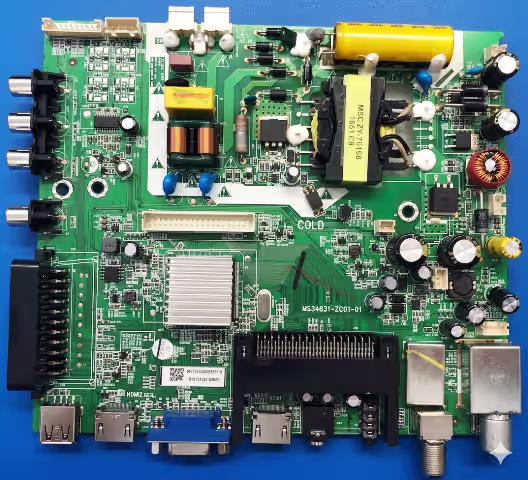
Main Board Reference
Identify the MS34631-ZC01-01 board layout below. Locate the 25Q64 SPI flash (8-pin SOIC near the main SOC), the LVDS header, and the tuner module before starting any repair procedure.
Known Issues & Symptoms
The following faults on the TELEFUNKEN TF-LED32S37T2 (board MS34631-ZC01-01) are caused by SPI memory corruption and are resolved by reflashing this dump:
- Stuck on TELEFUNKEN Logo / Infinite Boot Loop — TV displays logo then restarts endlessly. Boot sector in 25Q64 is corrupted.
- Completely Dead — No Standby LED — Main board receives power but MCU cannot initialize due to blank or corrupted flash content.
- Sound Present, No Picture — Audio outputs normally but LVDS data to LSC320AN10-H panel is absent. Panel timing configuration in flash is damaged.
- No Signal on All Inputs (HDMI / AV / USB / Antenna) — Source detection firmware block is corrupted; all inputs report “No Signal.”
- OSD Menu Freezes / Remote Unresponsive — UI firmware partially corrupted; on-screen display loads then locks up or does not render.
- Backlight Shuts Off After 2–3 Seconds — Protection routine triggers due to incorrect backlight voltage parameters stored in SPI after a power surge.
- Channel List & Settings Lost After Power Off — EEPROM region within SPI is corrupted; user data cannot persist across power cycles.
- Bricked After USB Software Update Attempt — Partially written firmware from interrupted update leaves the flash in an unusable state.
- Random Resets During Operation — Intermittent CRC failures reading corrupted flash sectors cause the main SOC to fault and reboot.
- Audio Distortion or No Sound — Audio codec initialization data in firmware is damaged, causing garbled output or silence on all audio paths.
Diagnostic & Repair Protocol
Phase 1 — Safety & Visual Inspection
- Disconnect AC mains and discharge all capacitors. Wait minimum 60 seconds before handling the PCB.
- Remove the rear panel and visually inspect the MS34631-ZC01-01 main board for swollen capacitors, burnt traces, cracked solder joints, or heat-damaged ICs.
- Measure PSU output rails: 5V standby (±0.25V), 12V main (±0.6V), and LED backlight driver voltage. If any rail is out of tolerance, repair the power supply first.
- Inspect the LVDS flat cable from main board to LSC320AN10-H panel. Reseat both ends firmly. Check for pin corrosion or torn conductors.
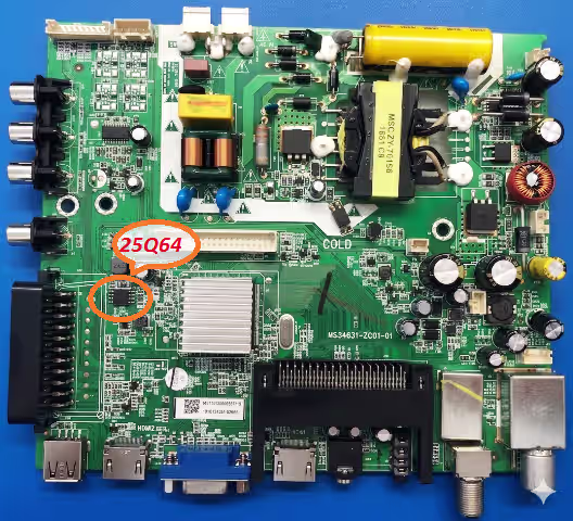
Phase 2 — SPI Flash Chip Identification
- Locate the 25Q64 SPI flash — an 8-pin SOIC chip typically positioned near the main SOC processor on the MS34631-ZC01-01 board.
- Confirm the chip marking: Winbond W25Q64 or compatible equivalent (GD25Q64, XM25QH64, EN25QH64). Capacity must be 64Mbit (8MB).
- Choose your method: In-circuit (ISP) programming using the RT809H SOP8 test clip — OR — desolder the chip and program in a ZIF/SOP8 socket adapter.
- If using ISP method, disconnect the main power supply connector from the board to prevent back-powering the SOC during programming.
Phase 3 — Backup, Erase & Flash
- Connect the RT809H programmer to the 25Q64. Launch the RT809H software and auto-detect the flash IC. Verify the detected chip matches 25Q64 / 8MB.
- Read the current flash content and save as
backup_original_TF-LED32S37T2.bin. Store this backup on a separate drive — you may need it for rollback. - Download the firmware dump from the link below. Verify the file size is exactly 8,388,608 bytes (8MB).
- Erase the entire chip (full chip erase), then write the downloaded .bin file to the 25Q64.
- Run a Verify operation immediately after writing. The software must report Verify OK — 0 errors. If verification fails, erase and reflash. If it fails again, replace the SPI chip.
Phase 4 — Post-Flash Testing & Validation
- Disconnect the programmer, reconnect PSU connectors, and reassemble. Power on the TV — the TELEFUNKEN logo should appear within 5 seconds and boot to home screen in 10–18 seconds.
- Perform a Factory Reset immediately: Menu → System → Factory Reset → Confirm. This initializes all EEPROM parameters to default values matching the panel and tuner configuration.
- Input Test: Connect devices to each HDMI port, AV input, and USB port. Verify signal detection and proper image/audio output on every input.
- Antenna Scan: Connect an RF signal and run DVB-T2 auto-scan. Verify channels are found, stored, and retained after power cycling.
- Backlight Stress Test: Set brightness to maximum, run for 10 minutes. Then set to minimum. Confirm no flicker, shutdown, or abnormal current draw.
- Audio Validation: Test internal speakers, headphone output (if applicable), and HDMI audio return. Confirm no distortion or imbalance.
- Power Cycle Test: Turn the TV off and on 5 times via remote. Confirm consistent boot, settings retention, and stable standby LED behavior.
SPI Flash Index — Pin Reference
Confirm correct pin-1 orientation on the 25Q64 SPI chip before connecting the RT809H ISP clip. Incorrect orientation will result in failed detection or potential chip damage.
Video Tutorial — Flashing Guide
Watch the complete firmware flashing procedure for the MS34631-ZC01-01 main board. Covers SPI chip location, RT809H wiring, software configuration, write/verify process, and post-flash boot test.
⬇ Download SPI Firmware Dump
MS34631-ZC01-01 • TELEFUNKEN TF-LED32S37T2 • 25Q64 Full Binary • 8MB
🔓 Step 1 — Unlock Download⬇ Step 2 — Download Firmware (.bin) ⚙ Click Step 1 first to unlock. Step 2 appears after — then click to download the .bin file.
File size: 8,388,608 bytes (8MB) • Format: Raw SPI Binary
Frequently Asked Questions
What problems does this firmware dump resolve?
This dump fixes stuck logo, boot loop, dead/no-standby, no picture with sound, no signal on HDMI/AV, OSD freeze, backlight auto-shutdown, EEPROM data loss, bricked-after-update, random resets, and audio faults on the TELEFUNKEN TF-LED32S37T2 with MS34631-ZC01-01 board.
Which programmer do I need?
The RT809H universal programmer is recommended. Connect to the 25Q64 via SOP8 clip (ISP) or desolder to a socket adapter. Alternatives: RT809F, CH341A — but RT809H offers the best auto-detection and verify reliability for this chip.
Is this firmware tested and verified?
Yes. The dump was read from a known-good working TELEFUNKEN TF-LED32S37T2 unit, then written to a faulty unit and verified. Both read-back and functional tests confirmed 100% operational status.
What if the TV still doesn’t work after flashing?
If the dump writes and verifies successfully but the TV remains faulty, suspect hardware failure: dead main SOC, failed power MOSFET, shorted backlight LED strip, damaged LVDS panel, or defective tuner module. The SPI dump restores software — it cannot repair physical component damage.
Can I use this dump on a different panel or board revision?
No. This dump is calibrated specifically for the MS34631-ZC01-01 board with LSC320AN10-H panel. Using it on a different panel may cause no display, incorrect resolution, or backlight damage. Always match both board and panel model exactly.
What file size should the dump be?
Exactly 8,388,608 bytes (8MB / 64Mbit). If your downloaded file is a different size, the download is corrupt — re-download the file.