Welcome to the definitive firmware resource for the Samsung UE40H6200AW television. This page provides technicians with a verified, ready-to-flash BN41-02156A firmware dump covering both the SPI 25Q40 memory and EEPROM 24C512 chip. Every file has been read, written, and boot-tested on actual hardware to ensure complete reliability before being made available for download.
Whether you are dealing with a dead set stuck on the Samsung logo, a black screen with active backlight, or a recurring restart loop, this dump is engineered to restore full factory operation. Follow the diagnostic protocol below, then proceed to the secure download section.
Technical Specifications
| Brand | Samsung |
|---|---|
| TV Model | UE40H6200AW |
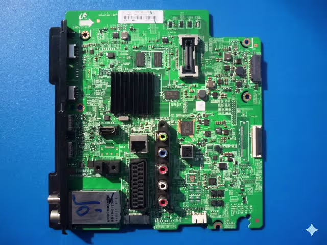
| Main Board | BN41-02156A |
| Panel | CY-GH040CS |
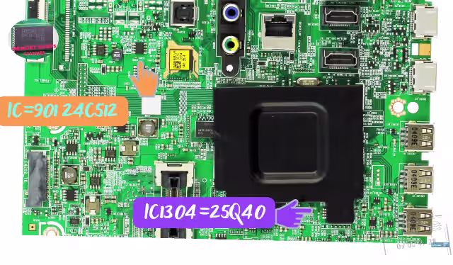
| SPI Flash IC | 25Q40 (4 Mbit) |
| EEPROM IC | 24C512 (512 Kbit) |
| Programmer | RT809H Universal Programmer |
| Firmware Status | Tested & 100% Working |
| File Format | .bin (binary dump) |
| Compatibility | BN41-02156A with CY-GH040CS panel only |
Known Issues Resolved by This Firmware
The following symptoms on the Samsung UE40H6200AW with BN41-02156A main board are directly caused by corrupted SPI or EEPROM data. Flashing the verified dump resolves each issue:
- Stuck on Samsung Logo: TV powers on, displays the boot logo, and freezes indefinitely. Caused by corrupted boot sector in the 25Q40 SPI flash.
- No Boot / Dead Set (Standby LED On): The standby indicator lights up, but the TV fails to initialize. Main processor cannot read valid firmware from SPI memory.
- Black Screen with Backlight Active: Backlight turns on, but no image or OSD appears. Panel initialization data in firmware is corrupted or missing.
- Repeated Restart Loop: TV continuously cycles through power-on and reboot. Watchdog timer triggers due to incomplete firmware execution.
- No Signal on All Inputs (HDMI / AV / USB): Tuner and input processing modules fail to load. Input configuration block in EEPROM is corrupted.
- Software Update Failure: USB update process fails or bricks the TV. Incomplete OTA or USB update left SPI flash in a partially written state.
- EEPROM Corruption (Wrong Settings / Factory Reset Loop): TV resets to factory settings after every power cycle or displays incorrect service menu values.
- No Audio Output: Picture is visible but audio is absent on all outputs. Audio codec initialization parameters corrupted in firmware.
Diagnostic & Repair Protocol
Before flashing firmware, follow this systematic diagnostic protocol to confirm the root cause and ensure a successful repair.
Phase 1 — Visual Inspection & Power Verification
Inspect the Main Board
Remove the back cover and visually examine the BN41-02156A board for burnt components, swollen capacitors, cold solder joints, or corrosion near the SPI flash and EEPROM ICs.
Verify Power Supply Voltages
Measure standby voltage (5V STB) and main operating voltages (12V, 3.3V, 1.8V, 1.2V core) with a multimeter. Ensure all rails are within 5% tolerance before proceeding.
Check Standby LED Behavior
Observe the front LED pattern: solid red indicates standby ready, blinking patterns indicate specific error codes. No LED at all points to a power supply fault rather than firmware.
Phase 2 — SPI Flash & EEPROM Reading
Desolder or Use In-Circuit Clip
For the 25Q40 SPI flash, use a SOIC8 test clip or carefully desolder the chip. For the 24C512 EEPROM, an in-circuit clip is usually sufficient if you isolate the data lines.
Read Current Firmware with RT809H
Connect the chip to the RT809H programmer. Select the correct IC model (W25Q40 or equivalent for SPI, AT24C512 for EEPROM). Perform two consecutive reads and compare checksums to verify read integrity.
Analyze the Dump
Open the read file in a hex editor. A valid SPI dump should not be all 0xFF (blank) or all 0x00. Check for recognizable header patterns. A corrupted dump confirms firmware is the failure point.
Phase 3 — Firmware Flashing
Erase the Chip
Perform a full chip erase on the 25Q40 SPI flash before writing. Verify the blank check passes (all bytes 0xFF).
Write the Verified Dump
Load the downloaded BN41-02156A firmware .bin file into the RT809H software. Write to the chip and wait for completion. Do not interrupt the process.
Verify After Writing
Perform a read-back verification. The RT809H software will compare the written data against the source file byte by byte. A 100% match confirms successful programming.
Resolder & Test
Resolder the SPI chip (if desoldered), reassemble the board, and power on the TV. The Samsung logo should appear followed by normal boot. Allow 1-2 minutes for initial setup.
Video Tutorial — Firmware Flash Guide
Watch the complete step-by-step process for reading and writing the BN41-02156A firmware using the RT809H programmer:
Download BN41-02156A Firmware Dump
SPI 25Q40 + EEPROM 24C512 binary files • Tested on Samsung UE40H6200AW • RT809H compatible
Click once to verify access, then click again to start download. File size: ~512 KB
Frequently Asked Questions
What programmer is needed for BN41-02156A firmware flashing?
The RT809H universal programmer is recommended. It supports both the SPI 25Q40 flash and the 24C512 EEPROM. Use a SOIC8 clip or adapter for in-circuit or off-board programming.
Is this BN41-02156A firmware dump tested?
Yes. This firmware dump has been extracted from a known-good Samsung UE40H6200AW unit, verified for data integrity, flashed onto a faulty board, and confirmed to boot and operate correctly with the CY-GH040CS panel.
What issues does the BN41-02156A firmware fix?
It resolves stuck on logo, no boot, black screen with backlight, repeated restart loop, no signal on all inputs, software update failure, EEPROM corruption, and no audio output issues caused by corrupted memory data.
Can I use this dump with a different panel?
This dump is specifically configured for the CY-GH040CS panel. Using it with a different panel may result in no picture, incorrect gamma, or panel timing errors. Always match both the main board and panel model.