For Technician Use Only
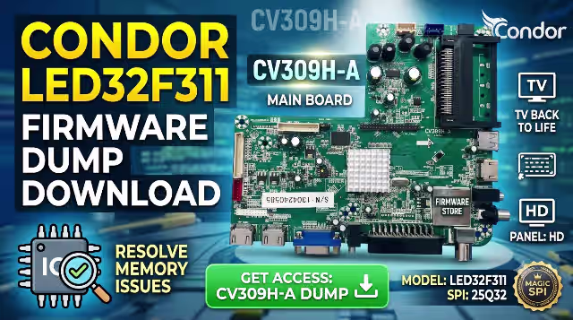
CV309H-A Firmware Dump
CONDOR LED32F311 — SPI 25Q32 Memory Repair File — Tested & Verified
⚙ Firmware Specifications
Brand
CONDOR
Model
LED32F311
Main Board
CV309H-A
Panel Type
HD Panel
SPI Memory
25Q32
Programmer
RT809H
Status
Tested 100%
Updated
08 June 2026
🔎 SPI Memory Chip Location
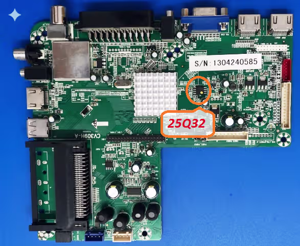
SPI 25Q32 memory chip location on the CV309H-A main board
🔧 Common Issues Resolved
The following symptoms on the CONDOR LED32F311 with CV309H-A board are resolved by reflashing the SPI 25Q32 dump:
- Dead TV — No power, no standby LED response after power supply verification
- Boot loop — TV stuck on CONDOR logo screen, continuously restarting
- No display — Backlight is ON but screen remains black with no OSD
- EEPROM corruption — Erratic behavior, random shutdowns, settings not saving
- Channel auto-search failure — Tuner not scanning or storing channels
- No audio output — Picture works but sound is completely absent
- OSD menu freeze — Menu appears but TV becomes unresponsive to remote commands
- Software bricked — Failed USB update leaving the TV non-functional
📋 Diagnostic & Repair Protocol
- Visual Inspection: Examine the CV309H-A board for burnt components, swollen capacitors, cracked solder joints, or physical damage before proceeding with firmware work.
- Power Supply Verification: Confirm all voltage rails from the PSU are within specification (5V, 12V, 3.3V). Use a multimeter to test standby and active voltages at the main board connector.
- Identify the SPI Chip: Locate the 25Q32 SPI flash memory on the CV309H-A board using the reference image above. Verify the chip marking matches 25Q32 (W25Q32, GD25Q32, or equivalent).
- Desolder the SPI Chip: Carefully remove the 25Q32 chip using a hot air rework station at 320-350 degrees Celsius. Apply flux generously and use tweezers to lift the chip once solder flows.
- Read & Backup Original Data: Place the chip in the RT809H programmer socket adapter. Read the existing firmware and save it as a backup file before writing new data.
- Erase the Chip: Perform a full chip erase using the RT809H software. Verify the erase operation completes with zero errors and the chip reads as blank (all 0xFF).
- Write the Firmware Dump: Load the downloaded CV309H-A SPI dump file into RT809H software. Write the firmware to the 25Q32 chip and verify the write by comparing checksums.
- Resolder the SPI Chip: Carefully solder the programmed 25Q32 chip back onto the CV309H-A board. Ensure proper pin alignment (pin 1 dot orientation) and clean flux residue with IPA.
- Power-On Test: Reconnect all cables, panel flex, and power supply. Power on the TV and verify it boots to the home screen with normal display output, audio, and remote response.
- Final Calibration: Perform initial channel scan setup, adjust picture and audio settings. Run the TV for 30 minutes minimum to confirm stability with no recurring issues.
⬇ Download Firmware Dump
Verified & Tested 100% Working
FileCV309H-A_25Q32.bin
Memory25Q32 (4MB)
ProgrammerRT809H
ChecksumVerified
Click once to continue, then click again to access the firmware file.
Compatible with RT809H, RT809F, TL866II Plus, and CH341A programmers.