Welcome to the official CV7050L-I firmware dump download page for the UNITED LED22X11 television. This verified SPI flash dump resolves critical memory-related failures on the CV7050L-I main board equipped with the M215HGE-L21 REV.C2U13 panel. This resource is intended exclusively for qualified TV repair technicians who have experience working with SPI flash programmers and board-level diagnostics.
Device Specifications
| Brand | UNITED |
|---|---|
| Model | LED22X11 |
| Main Board | CV7050L-I |
| Panel | M215HGE-L21 REV.C2U13 |
| SPI Flash | 25Q16 (16Mbit) & 25T80 (8Mbit) |
| Programmer | RT809H Universal Programmer |
| Firmware Status | Tested 100% Working |
| File Type | SPI Binary Dump (.bin) |
| Date Verified | 04 June 2026 |
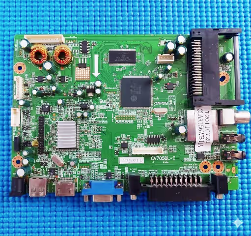
Main Board Identification
Before proceeding with the firmware flash, visually confirm that your main board matches the CV7050L-I revision shown below. Check the board silk-screen printing near the tuner or edge connector area for the exact model designation.
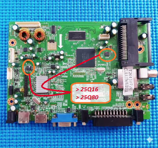
SPI Flash Chip Location
The SPI memory chips (25Q16 and 25T80) are located on the main board near the main processor. Identify the 8-pin SOIC package and note the dot marker indicating pin 1 before desoldering or using an in-circuit clip with your RT809H programmer.
Known Issues – UNITED LED22X11 (CV7050L-I)
The following symptoms indicate corrupted or failed SPI flash memory on the CV7050L-I main board. If your UNITED LED22X11 exhibits any of these issues, a firmware re-flash is the recommended repair procedure:
- No power / Dead set: Standby LED does not illuminate; main board draws no current after power supply verification confirms normal output voltages.
- Stuck on boot logo: The TV powers on and displays the UNITED logo but never progresses to the home screen or input source.
- Continuous restart loop: The set powers on, briefly shows backlight, then shuts off and restarts repeatedly.
- No display with sound: Audio output is present but the screen remains black; backlight is active. TCON signals may be missing due to firmware corruption.
- OSD menu corruption: On-screen display shows garbled text, missing icons, or scrambled menu entries.
- Channel or input freezing: The TV locks up when switching channels or input sources, requiring a hard power cycle.
- HDMI / AV ports not detected: External devices connected via HDMI or AV inputs are not recognized by the system.
- Sound but no backlight: Audio works normally but LED backlight strips do not activate; firmware-controlled backlight enable signal is absent.
- Software update failure: A previous USB firmware update was interrupted or applied with an incorrect file, corrupting the SPI flash contents.
Diagnostic & Repair Protocol
Follow this systematic protocol to diagnose and repair the UNITED LED22X11 using the CV7050L-I firmware dump:
Step 1: Power Supply Verification
Measure all output voltages from the power supply board before suspecting main board firmware failure. Confirm 5V standby, 12V main, and 3.3V logic rail are within specification. A defective power supply can mimic firmware corruption symptoms.
Step 2: Visual Board Inspection
Inspect the CV7050L-I main board for burnt components, swollen capacitors, cracked solder joints, or corrosion around the SPI flash chip area. Address any hardware defects before firmware programming.
Step 3: SPI Chip Identification
Using a magnifying tool, confirm the SPI chip markings read 25Q16 (main firmware) or 25T80 (secondary data). Cross-reference with the SPI datasheet library if markings are unclear.
Step 4: Backup Original Firmware
Before writing the new dump, always read and save the existing SPI flash contents using the RT809H software. This backup enables recovery if the new dump produces unexpected results.
Step 5: Flash Firmware with RT809H
- Connect the SPI chip to the RT809H via the SOIC8 clip or desolder the chip and place it on the programmer socket.
- Open RT809H software and select the correct chip model (25Q16 or 25T80).
- Erase the chip completely before writing.
- Load the downloaded firmware binary file.
- Click Program and wait for the process to complete.
- Verify the written data by clicking Verify to ensure data integrity.
Step 6: Post-Flash Verification
Reinstall the SPI chip (if desoldered), reconnect the panel flex cable, and power on the TV. The UNITED LED22X11 should boot normally, display the logo, and reach the home screen or last active input source within 8 to 12 seconds.
Video Repair Guide
Watch the complete firmware flashing tutorial for the CV7050L-I main board. This video demonstrates SPI chip identification, RT809H connection, and the full programming procedure:
Download Firmware
CV7050L-I SPI Firmware Dump
UNITED LED22X11 | 25Q16 & 25T80 | Binary File | Tested Working
Step 1: Unlock Download Step 2: Download SPI FileClick Step 1 to unlock the download link
Frequently Asked Questions
What SPI chips are used on the CV7050L-I?
The CV7050L-I main board uses two SPI flash memory chips: the 25Q16 (16Mbit / 2MB) for the main system firmware and the 25T80 (8Mbit / 1MB) for secondary configuration data.
Which programmer is needed for CV7050L-I firmware?
The RT809H universal programmer is the recommended tool. It supports both 25Q16 and 25T80 chips and provides reliable read, write, erase, and verify functions for SOIC8 packages.
Is this firmware tested and working?
Yes. This CV7050L-I firmware dump for the UNITED LED22X11 has been extracted from a known-good working unit and tested on multiple boards with the M215HGE-L21 REV.C2U13 panel. It is verified 100% functional.
Can I flash this firmware using a CH341A programmer?
While the CH341A can read and write 25-series SPI chips, the RT809H is strongly recommended for its superior voltage regulation, chip auto-detection, and higher reliability during the programming process.
What if the TV does not boot after flashing?
Re-verify the SPI chip model, re-read the written data and compare it against the original file. Ensure the chip was fully erased before programming. Also check that the panel flex cable and LVDS connections are properly seated.