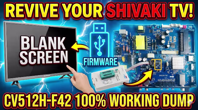
CV512H-F42 Firmware Dump for SHIVAKI LED 32-9000 TV
Tested & verified memory dump — resolve any SPI flash or boot failure on this main board. 100% working repair file for professional technicians.
Verified Working
📅 Updated: July 2025
📦 SPI: 25Q64 (8MB)
🔧 RT809H Programmer
⚠ Professional Technician Use Only
This firmware dump file is intended exclusively for qualified TV repair technicians. Incorrect flashing can permanently damage the main board. Ensure proper ESD precautions. The author assumes no liability for misuse or damage resulting from improper application.
1
Board & Firmware Specifications
TV Brand / Model
SHIVAKI LED 32-9000
Main Board
CV512H-F42
LCD Panel
LCM32C
Screen Size
32″ LED
Resolution
1366 × 768 (HD Ready)
SPI Flash IC
25Q64 (W25Q64 / GD25Q64 / MX25L6406E)
Flash Size
8 MB (64 Mbit)
Programmer
RT809H
Programming Method
SPI Flash – Direct Read/Write
Firmware Status
✔ Tested 100% Working
File Type
.bin (Binary dump)
Compatibility
Panel-Specific — LCM32C
2
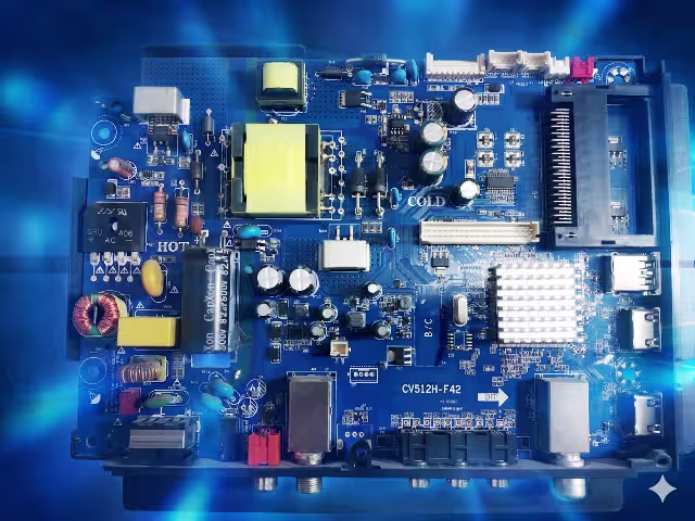
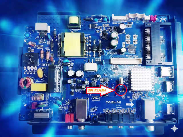
Main Board & SPI Flash Identification
Identify your board revision and locate the SPI flash memory chip before proceeding with the firmware dump procedure.
CV512H-F42 Main Board — Top ViewSPI Flash 25Q64 — Chip Location
3
Common Issues & Symptoms (CV512H-F42)
The following symptoms indicate corrupted or failed SPI flash memory on the CV512H-F42 main board. This firmware dump resolves all listed issues:
1. Dead TV / No Power Response: Power LED does not illuminate. TV shows no sign of life despite verified power supply output. Caused by corrupted boot sector in SPI flash memory.
2. Stuck on Boot Logo / Endless Boot Loop: TV powers on, displays the SHIVAKI logo, then restarts repeatedly. Firmware initialization sequence fails to complete due to corrupted system data.
3. Backlight On, No Display (Black Screen): LED backlight activates but screen remains completely black. No OSD menu, no channel display. Main processor fails to initialize display output.
4. No Audio Output: Picture may display correctly but all audio channels are silent. Volume controls unresponsive. Audio codec initialization data corrupted in firmware.
5. Remote Control Not Responding: TV is powered on but does not respond to any IR remote commands. Front panel buttons may or may not function. IR protocol data corrupted.
6. HDMI / AV Ports Not Detecting Input: Connected devices are not recognized on any input port. Source menu shows no signal on all inputs. I/O initialization failure in firmware.
7. OSD Menu Corruption / Garbled Text: On-screen display shows scrambled characters, wrong language defaults, or menu items are missing. Font and language data corrupted in flash.
8. TV Turns Off Immediately After Power On: LED blinks momentarily then TV shuts down within 1-3 seconds. Protection circuit triggered by firmware fault detection.
9. Channel Scan Failure / No Tuner Detection: Auto-scan finds zero channels. Tuner initialization parameters lost from memory corruption.
10. Frozen Screen / System Hang: Display freezes on a single frame. No response to any input. Requires hard power cycle. Indicates runtime firmware corruption.
4
Diagnostic & Repair Protocol
Follow this step-by-step procedure to successfully program the firmware dump onto the CV512H-F42 main board using an RT809H universal programmer:
Step 1 Safety First — Disconnect AC Power: Unplug the TV completely from mains power. Wait at least 30 seconds for capacitors to discharge. Use an ESD wrist strap throughout the entire procedure to prevent static damage to sensitive components.
Step 2 Access the Main Board: Remove the rear panel screws and carefully detach the back cover. Identify the CV512H-F42 main board. Locate the 25Q64 SPI flash chip — it is typically an 8-pin SOIC package positioned near the main processor. Refer to the board image above for exact location.
Step 3 Desolder the SPI Flash IC: Using a hot air rework station set to 320-350°C with medium airflow, carefully desolder the 25Q64 chip from the PCB. Apply flux generously before heating. Use tweezers to gently lift the chip once solder is molten. Clean pads with solder wick after removal.
Step 4 Connect to RT809H Programmer: Place the desoldered 25Q64 chip into the appropriate SOP8 socket adapter on the RT809H programmer. Ensure correct pin 1 orientation (dot marking on chip aligns with pin 1 indicator on socket). Connect RT809H to your computer via USB.
Step 5 Erase the Original Firmware: Open the RT809H software on your PC. Auto-detect the chip or manually select W25Q64 / GD25Q64 from the chip database. Click “Erase” to perform a full chip erase. Verify the erase was successful — all bytes should read 0xFF.
Step 6 Load & Write the Firmware Dump: Click “Open File” and browse to the downloaded .bin firmware file. Click “Program” (Write) to flash the firmware onto the chip. The process takes approximately 60-90 seconds for 8MB. Do NOT interrupt the process.
Step 7 Verify the Written Data: After programming completes, click “Verify” to compare the chip contents against the source file byte-by-byte. The verification must show 100% match. If verification fails, erase and reprogram. Use a different chip if failures persist.
Step 8 Resolder the SPI Flash IC: Remove the chip from the programmer socket. Apply fresh flux to the PCB pads. Position the 25Q64 chip with correct pin 1 alignment. Solder using a fine-tip iron at 320°C or hot air at 300°C. Inspect all 8 pins under magnification for bridges or cold joints.
Step 9 Reassemble & Power Test: Reconnect all ribbon cables and wire harnesses. Reattach the rear panel. Connect AC power and switch on the TV. The first boot may take 15-30 seconds longer than normal as the system initializes. If the TV boots successfully to the home screen, the repair is complete.
Step 10 Post-Flash Configuration: After successful boot, perform a Factory Reset from the OSD menu. Run an Auto Channel Scan. Verify all inputs (HDMI, AV, USB), audio output, and remote control functionality. Test for 30+ minutes to confirm stability.
5
Video Tutorial — Firmware Programming Guide
Watch the complete visual walkthrough demonstrating the SPI flash removal, programming with RT809H, and successful board repair:
Download Firmware Dump
CV512H-F42 — SHIVAKI LED 32-9000 — SPI 25Q64 Binary
Step 1: Click the button above to verify you’re human. Step 2: Click the green button that appears to access the direct download link.
⚠ File is for CV512H-F42 with LCM32C panel ONLY. Do not flash on other panel types.
Disclaimer: All firmware files are provided for professional repair purposes only. Ensure compatibility with your exact board revision and panel model before flashing. We are not responsible for any damage caused by incorrect use of these files. All trademarks belong to their respective owners.
Contains information related to marketing campaigns of the user. These are shared with Google AdWords / Google Ads when the Google Ads and Google Analytics accounts are linked together.
90 days
__utmz
Contains information about the traffic source or campaign that directed user to the website. The cookie is set when the GA.js javascript is loaded and updated when data is sent to the Google Anaytics server
6 months after last activity
__utmc
Used only with old Urchin versions of Google Analytics and not with GA.js. Was used to distinguish between new sessions and visits at the end of a session.
End of session (browser)
__utmb
Used to distinguish new sessions and visits. This cookie is set when the GA.js javascript library is loaded and there is no existing __utmb cookie. The cookie is updated every time data is sent to the Google Analytics server.
30 minutes after last activity
__utmt
Used to monitor number of Google Analytics server requests
10 minutes
__utma
ID used to identify users and sessions
2 years after last activity
__utmv
Contains custom information set by the web developer via the _setCustomVar method in Google Analytics. This cookie is updated every time new data is sent to the Google Analytics server.
2 years after last activity
_gat
Used to monitor number of Google Analytics server requests when using Google Tag Manager
1 minute
_gid
ID used to identify users for 24 hours after last activity
24 hours
_ga_
ID used to identify users
2 years
_gali
Used by Google Analytics to determine which links on a page are being clicked
30 seconds
_ga
ID used to identify users
2 years
__utmx
Used to determine whether a user is included in an A / B or Multivariate test.