 FOR TECHNICIAN USE ONLY
TESTED 100% WORKING
FOR TECHNICIAN USE ONLY
TESTED 100% WORKING
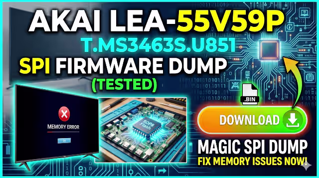
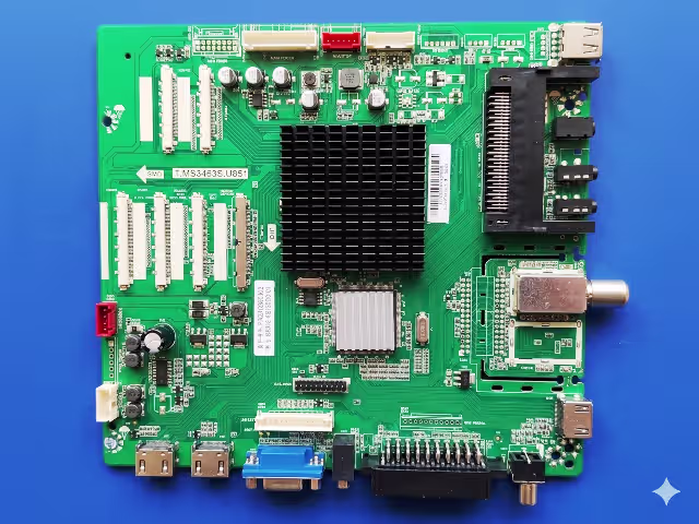
This page provides a verified and tested SPI firmware dump for the T.MS3463S.U851 main board installed in the AKAI LEA-55V59P 55-inch LED television. The bin file targets the 25GD64 SPI flash memory and is intended exclusively for qualified electronics technicians performing board-level memory repair using the RT809H universal programmer.
Firmware Specifications
| Brand | AKAI |
| Model | LEA-55V59P |
| Main Board | T.MS3463S.U851 |
| Panel | LSF550FN09-L02 |
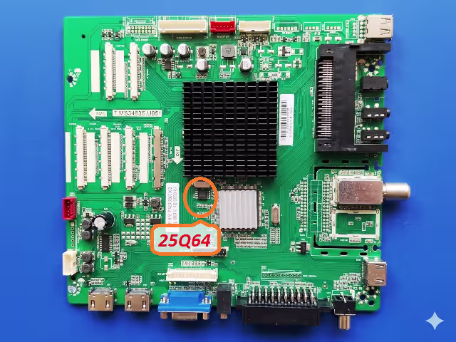
| SPI Flash IC | 25GD64 (64Mbit / 8MB) |
| Programmer | RT809H Universal Programmer |
| File Type | BIN (Raw SPI Dump) |
| Status | Verified TESTED 100% |
Common Issues Resolved by This Firmware
The following symptoms on the AKAI LEA-55V59P with the T.MS3463S.U851 board indicate a corrupted or failing SPI flash memory. Reflashing with this verified dump resolves these faults:
- TV does not power on — stuck in standby mode with LED indicator on
- Continuous boot loop — TV restarts repeatedly without reaching home screen
- Backlight turns on but no image displayed on screen — black screen with sound
- Stuck on AKAI logo screen during boot — firmware hangs at splash
- EEPROM data corruption — settings not saving or factory reset loop
- No audio output on any source — internal speakers and headphone jack silent
- HDMI and AV input ports not detected — no signal message on all inputs
- Remote control completely unresponsive — IR receiver not processing commands
- OSD menu not appearing or partially rendered — graphical corruption
- Channel auto-scan failure — tuner not detecting any broadcast signals
Diagnostic and Repair Protocol
Follow this standardized procedure to diagnose the memory fault and flash the replacement firmware onto the SPI chip:
Phase 1 — Initial Diagnosis
- Perform a visual inspection of the T.MS3463S.U851 main board for burnt components, swollen capacitors, or cracked solder joints around the power supply section and SPI flash area.
- Verify the power supply output voltages — confirm 5V, 12V, and 3.3V rails are within tolerance before suspecting firmware corruption.
- Test the backlight inverter section independently to rule out LED driver failure as the cause of a black screen.
- If the board passes power rail checks but exhibits boot failure or logo-stuck symptoms, the SPI flash memory is the primary suspect.
Phase 2 — SPI Chip Extraction
- Power off the TV and disconnect from mains supply. Discharge all capacitors on the main board before handling.
- Locate the 25GD64 SPI flash chip on the T.MS3463S.U851 board — refer to the SPI chip location image above for exact position.
- Apply flux generously around all pins of the SPI chip and desolder using a hot air rework station at 320 to 350 degrees Celsius with medium airflow.
- Clean the chip pads on both the board and the removed IC using solder wick and isopropyl alcohol.
Phase 3 — Firmware Flashing
- Place the 25GD64 chip into the correct SOP8 socket adapter on the RT809H programmer. Ensure pin 1 orientation matches the socket marking.
- Launch the RT809H software on your computer. Select the chip model as GD25Q64 (GigaDevice 25GD64 equivalent) from the IC database.
- Click Read to verify the programmer detects and communicates with the chip successfully.
- Click Erase to perform a full chip erase — confirm the erase verification passes before proceeding.
- Load the downloaded BIN file into the programmer software buffer and click Write to flash the firmware.
- After writing completes, click Verify to compare the chip contents against the source file — ensure zero mismatches.
Phase 4 — Reassembly and Verification
- Resolder the programmed 25GD64 chip back onto the T.MS3463S.U851 board using proper flux and soldering technique. Inspect all joints under magnification.
- Reconnect all ribbon cables, LVDS cable to the LSF550FN09-L02 panel, backlight connectors, and power supply harness.
- Power on the TV and verify successful boot to the home screen. Confirm all inputs, audio output, OSD menu, remote control, and channel tuning functions operate correctly.
- Perform a factory reset from the service menu to initialize all EEPROM parameters with clean default values.
Video Repair Guide
Watch the complete visual walkthrough for the T.MS3463S.U851 firmware dump and SPI memory repair process:
Download Firmware File
SPI BIN dump for T.MS3463S.U851 — AKAI LEA-55V59P
Chip: 25GD64 • Programmer: RT809H • Verified Working
File: T.MS3463S.U851_AKAI_LEA-55V59P_25GD64.bin • Click the button — a new tab opens first, then your download begins automatically.