TP.MS3663S.PB818 Firmware Dump – Polarline 32PL54TC USB Update
Published: · Last Updated:
Download the TP.MS3663S.PB818 firmware dump for Polarline 32PL54TC LED TV. Get free access to this memory repair file and restore your dead or malfunctioning television via USB update or SPI programmer. This firmware has been tested and verified 100% working by professional TV repair technicians.
Main Board Identification

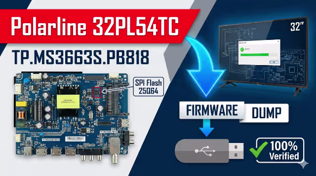
TP.MS3663S.PB818 main board – Polarline 32PL54TC
Firmware Specifications
| Board Model | TP.MS3663S.PB818 |
|---|---|
| TV Model | Polarline 32PL54TC |
| Screen Size | 32 Inch LED |
| Resolution | 1366 × 768 (HD Ready) |
| Main Processor | MStar MS3663S |
| Flash Memory | SPI NOR Flash (25Q64 / 25Q128) |
| Dump Size | 8 MB (64 Mbit) |
| Update Method | USB / SPI Programmer |
| File Format | .bin (binary dump) |
| Status | ✔ Tested 100% Working |
| Date | 04/05/2026 |
SPI Flash Memory Location

SPI Flash chip location on TP.MS3663S.PB818 board
Common Issues – Polarline 32PL54TC
Below are the most frequently reported problems with the Polarline 32PL54TC using the TP.MS3663S.PB818 board that can be resolved by reflashing or replacing the SPI memory firmware:
🔴 Dead TV – No Power Indicator
TV does not turn on and no standby LED is visible. Commonly caused by a corrupted boot sector in the SPI flash memory or a failed power supply regulation circuit.
🔴 Stuck on Logo / Boot Loop
TV powers on and displays the Polarline logo but never reaches the home screen. Restarts continuously. The system partition of the firmware is corrupted and needs a fresh dump.
🔴 Black Screen with Backlight On
Backlight illuminates but the screen remains completely black with no OSD. LVDS configuration data or panel initialization parameters in the firmware are corrupted or mismatched.
🔴 No Audio Output
Picture displays normally but no sound from internal speakers or headphone jack. Audio DAC configuration and amplifier initialization data in firmware require restoration.
🔴 Remote Control Not Responding
TV ignores all IR remote commands. The IR protocol mapping and key code tables in the SPI flash are corrupted. Physical power button on the chassis may still function.
🔴 HDMI / AV Input Not Detected
External devices connected via HDMI, AV, or USB are not recognized. Input source switching fails completely. Port mapping and EDID data in SPI flash is corrupted.
🔴 OSD Menu Garbled or Distorted
On-screen display shows corrupted text, wrong language characters, or graphical artifacts. Font tables, menu structure, and localization data in firmware need full restoration.
🔴 Failed Software Update – Bricked Unit
A previous USB firmware update was interrupted by power loss, leaving the TV in a completely unbootable state. Only a clean SPI dump via programmer can recover the board.
🔴 Channel Tuner Malfunction
TV cannot scan or store channels. Tuner initialization parameters and channel database in flash memory are corrupted. Fresh firmware restores full tuner functionality.
🔴 Backlight Flickering or Unstable
Screen backlight flickers, dims randomly, or turns off intermittently. PWM backlight control parameters stored in the firmware configuration area need to be reset to factory defaults.
Diagnostic & Repair Protocol
Phase 1 — Visual Inspection & Voltage Diagnosis
- Disconnect the TV from mains power and remove the back cover. Perform a thorough visual inspection of the TP.MS3663S.PB818 main board for burnt components, swollen or leaking electrolytic capacitors, cracked solder joints, or damaged PCB traces.
- Inspect the power supply board for any signs of failure — bulging capacitors, burnt resistors, or discolored areas around the transformer and rectifier section.
- Reconnect power and use a digital multimeter to check all power rails: 5V standby, 12V main supply, 3.3V logic, and 1.8V core voltage. Document any deviations from expected values.
- Verify the LVDS flat cable between the main board and the T-CON board for proper seating, continuity, and physical damage. Reseat the connector firmly.
- Confirm the SPI flash IC part number on the chip marking — typically GD25Q64, W25Q64, or MX25L6406E. Verify the capacity matches the dump file size (8 MB / 64 Mbit).
- Check the IR sensor module cable and the front panel button board ribbon cable for secure connections.
Phase 2 — Firmware Flashing via USB Update
- Download the TP.MS3663S.PB818 firmware dump file from the download section below.
- Extract the .bin file from the compressed archive. Do not rename the extracted file.
- Obtain a reliable USB 2.0 flash drive (8 GB maximum recommended). Format it to FAT32 file system with default allocation unit size.
- Copy the firmware .bin file to the root directory of the USB drive. Ensure no other files are present on the drive.
- With the TV unplugged from mains power, insert the prepared USB drive into the TV’s USB port.
- Plug in the power cable and press the power button. The firmware update process should initiate automatically — a progress bar on screen or a rhythmic flashing of the front panel LED will indicate the write operation is in progress.
- Do not unplug the TV, remove the USB drive, or press any buttons during the entire flashing process. Typical duration is 2 to 5 minutes depending on file size.
- The TV will restart automatically upon successful completion. Wait for a full boot cycle, then remove the USB drive.
Phase 3 — Firmware Flashing via SPI Programmer
- If the USB update method fails (completely dead board, corrupted boot loader, or no screen output), proceed with direct SPI programming using a hardware programmer such as CH341A, RT809H, RT809F, or TL866II Plus.
- Disconnect the main board from all other boards (power supply, T-CON, speakers, IR sensor). Optionally remove the board from the chassis for easier access.
- Locate the SPI flash IC on the board (refer to the SPI Flash image above). Use a SOIC8 test clip to connect without desoldering, or carefully desolder the chip using a hot air rework station at 280–320°C.
- Read the existing flash content first and save a complete backup copy before performing any erase or write operation.
- Perform a full chip erase, then write the downloaded .bin firmware dump file to the chip.
- After writing, perform a verify operation — the programmer should compare the written data byte-by-byte against the source file. Ensure checksum match with zero errors.
- If the chip was desoldered, carefully resolder it back to the PCB pads using flux and a fine-tip soldering iron or hot air at 300°C. Inspect all 8 pins under magnification for bridges or cold joints.
- Reconnect all board-to-board cables and reassemble the TV.
Phase 4 — Post-Flash Verification & Testing
- Power on the TV and verify the Polarline boot logo appears within 3–5 seconds.
- Confirm the OSD main menu loads correctly with proper language, correct menu structure, and no graphical corruption.
- Test all input sources sequentially: HDMI 1, HDMI 2, AV composite, USB media playback, and RF antenna/tuner input.
- Verify audio output — test internal speakers at various volume levels and check the headphone/audio out jack if available.
- Confirm full IR remote control responsiveness — test power, volume, channel, menu, source, and navigation buttons.
- Verify backlight brightness adjustment works correctly through the full range without flickering or instability.
- Run an automatic channel scan to confirm the TV tuner functions correctly and stores channels.
- Access the factory service menu (if applicable) and perform a factory reset to initialize all default configuration values and calibration data.
- Allow the TV to run for a minimum of 30 minutes continuously to confirm thermal stability and absence of intermittent faults.
Video Tutorial
Watch the complete step-by-step firmware flashing tutorial for the TP.MS3663S.PB818 board:
Download Firmware
TP.MS3663S.PB818 – Polarline 32PL54TC
Firmware Dump File (.bin)
⬇ Download Firmware
Step 1: Click “Unlock Download” — a new tab will open.
Step 2: Return here and click “Download Firmware” to get the file.
Important Notes
- Verify the board model printed on the PCB matches TP.MS3663S.PB818 exactly before flashing. Similar model numbers like TP.MS3663S.PB801 or PB819 use different firmware.
- Check the SPI flash IC capacity — this dump file is designed for 8 MB (64 Mbit) flash chips. Using it on a 4 MB chip will fail; a 16 MB chip will require padding.
- If your panel resolution differs from 1366×768, you may need to adjust LVDS output settings via the service menu or use a panel-specific firmware variant.
- Always create a backup of the original SPI flash content before writing any new data.
- Use a stable and uninterrupted power source during the entire flashing process. A UPS is recommended for SPI programmer operations.
- After successful flashing, a factory reset is recommended to clear residual settings and initialize clean default values.
- This firmware is provided as-is for professional technician use only. The author assumes no liability for damage resulting from improper use.