JUC7.820.00194894 Firmware dump for CHANGHONG LED39E6300 TV . Fix it now!

JUC7.820.00194894 Firmwaredump for CHANGHONG LED39E6300 TV
https://t JUC7.820.00194894 Firmware Dump – CHANGHONG LED39E6300 | Download SPI Flash 25Q64
JUC7.820.00194894 mainboard firmware dump for CHANGHONG LED39E6300 TV – SPI 25Q64 memory repair download
Technician Use Only Verified Working
CHANGHONG × TV Tech Online

JUC7.820.00194894
Firmware Dump

📺 LED39E6300 🔧 SPI: 25Q64 ⚡ RT809H 📁 .bin File
Download Now
By 🟢 Firmware Status: 100% Tested

Firmware Overview

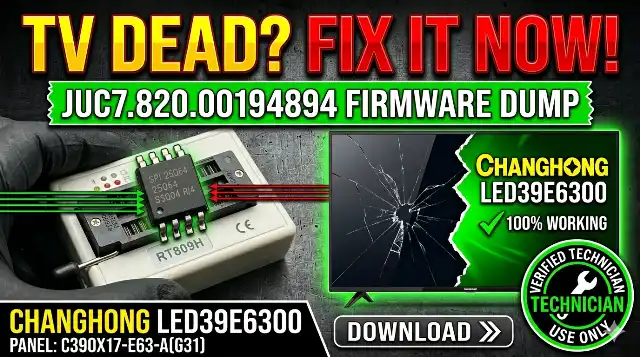
This page provides the JUC7.820.00194894 firmware dump for the CHANGHONG LED39E6300 television. The SPI flash memory dump has been extracted from the 25Q64 chip using the RT809H universal programmer and verified to be 100% functional. This file is intended exclusively for qualified TV repair technicians performing board-level diagnostics and memory chip replacement or reprogramming.

Technical Specifications

CHANGHONG LED39E6300 mainboard and firmware specifications
BrandCHANGHONG
TV ModelLED39E6300
MainboardJUC7.820.00194894
PanelC390X17-E63-A (G31)
SPI Flash IC25Q64 (64Mbit / 8MB)
ProgrammerRT809H Universal Programmer
Package TypeSOP8
Firmware Status✅ Tested 100% Working
File Type.bin (binary dump)

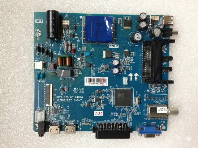
Mainboard Identification

Before downloading, confirm your mainboard matches the reference images below. The board number JUC7.820.00194894 is printed on the PCB surface near the main processor.

JUC7.820.00194894 mainboard for CHANGHONG LED39E6300 TV showing component layout and board number
Fig 1: JUC7.820.00194894 Mainboard – CHANGHONG LED39E6300

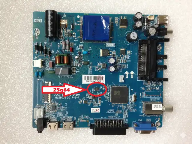
SPI Flash Chip Location

The 25Q64 SPI flash memory chip stores all firmware, boot data, EDID, and channel configurations. Locate the 8-pin SOP8 package on the mainboard as shown in the reference image below.

25Q64 SPI flash chip location on JUC7.820.00194894 mainboard highlighted for identification
Fig 2: SPI Flash 25Q64 Chip Location on JUC7.820.00194894

Common Issues & Symptoms

The following problems on the CHANGHONG LED39E6300 are typically caused by corrupted SPI flash data and can be resolved by reprogramming the 25Q64 chip with this firmware dump:

TV Stuck on Logo / Boot Loop
The TV powers on but freezes at the CHANGHONG logo screen and never reaches the home menu. This indicates corrupted boot sector data in the SPI flash. Re-flashing the 25Q64 chip resolves the boot loop.
No Picture – Backlight On (Black Screen)
Backlight activates but no image appears. The LVDS initialization data or panel timing configuration in the firmware may be corrupted. A fresh dump restores correct panel communication with C390X17-E63-A.
Dead Set – No Standby LED
If the power supply outputs are verified correct but the mainboard shows no signs of life, the corrupted SPI flash may prevent the main CPU from initializing. Flash a known-good dump to restore functionality. Also check for shorted components near the CPU.
TV Turns Off Immediately After Power On
The TV attempts to start but shuts down within 1-3 seconds. This is often a firmware-level protection trigger caused by corrupted system flags. Reprogramming the memory IC clears these flags.
No Sound – Picture OK
Audio processing parameters stored in flash may become corrupted. After ruling out hardware faults (speaker, audio amp IC), flashing the firmware restores default audio configuration.
Menu Not Responding / Remote Not Working
IR receiver and key mapping data in the SPI flash may be damaged. A clean firmware write restores remote control functionality. Verify the IR sensor hardware is functional before flashing.
HDMI / AV Inputs Not Detected
Input source detection relies on firmware-defined port configurations. Corrupted input mapping data causes the TV to not recognize connected devices. Re-flashing resolves input detection issues.

Diagnostic & Repair Protocol

Follow this systematic diagnostic procedure before flashing the firmware to ensure the root cause is indeed a corrupted SPI flash and not a hardware failure:

Pre-Flash Hardware Checks

  1. Inspect Power Supply: Measure all output voltages (5V standby, 12V/24V main). Confirm voltages are within ±5% tolerance under load. Do not proceed if PSU outputs are abnormal.
  2. Visual PCB Inspection: Examine the JUC7.820.00194894 mainboard for burnt components, bulging capacitors, cracked solder joints, or corrosion around the main IC and SPI flash area.
  3. Check Main Processor: Verify the CPU is not shorted to ground. Measure resistance between VCC and GND pins. A dead short indicates CPU failure—firmware flashing will not help.
  4. Test LVDS Cable & Panel: Verify the LVDS flat cable connection between the mainboard and C390X17-E63-A panel. Reseat the connector and inspect for damaged pins.
  5. Read Current SPI Dump: Before erasing, always read and save the existing 25Q64 content as a backup using the RT809H. This allows you to revert if needed.

Firmware Flashing Procedure (RT809H)

  1. Desolder the SPI Chip: Using a hot-air rework station at 320-350°C, carefully remove the 25Q64 SOP8 chip from the mainboard. Clean pads with flux and solder wick.
  2. Mount on Programmer: Place the 25Q64 chip into the SOP8 to DIP8 adapter and insert into the RT809H ZIF socket. Ensure pin 1 orientation is correct.
  3. Detect & Identify: Open RT809H software. Click “Auto Detect” or manually select W25Q64 (Winbond) / GD25Q64 (GigaDevice) from the chip list depending on your IC manufacturer.
  4. Full Erase: Perform a complete chip erase. Verify the erase operation completes successfully (all bytes 0xFF).
  5. Load Firmware File: Click “Open File” and browse to the downloaded JUC7.820.00194894 .bin firmware dump file.
  6. Write Firmware: Click “Program/Write” to flash the firmware onto the 25Q64 chip. Wait for the operation to complete without interruption.
  7. Verify Data: Click “Verify” to compare the chip contents against the source file. Ensure a 100% match with zero errors.
  8. Resolder the Chip: Carefully solder the 25Q64 back onto the JUC7.820.00194894 mainboard. Inspect solder joints under magnification for bridges or cold joints.
  9. Power On & Test: Reconnect the panel, power supply, and speakers. Power on the TV and verify normal boot sequence, picture, sound, and input functionality.
✅ Post-Flash Checklist: After successful flashing, verify: boot to home screen, remote control response, all HDMI/AV inputs, audio output, channel tuning, and OSD menu navigation. The TV may require initial setup (language, region) as factory defaults are restored.

Video Tutorial

Watch the complete firmware flashing tutorial for reference on the RT809H programming procedure and mainboard handling techniques:

Download Firmware Dump

📥 JUC7.820.00194894 – Firmware Dump File

SPI Flash: 25Q64 | Format: .bin | Programmer: RT809H
Status: ✅ Verified 100% Working

Step 2: Download Firmware (.bin)

Click Step 1 to unlock, then click Step 2 to download the file.

ℹ Important Notes: This firmware dump is for mainboard JUC7.820.00194894 only. Do not use on other CHANGHONG models or different mainboard revisions. Always verify board number before flashing. The file must be written to a 25Q64 SPI flash chip using the RT809H programmer.

Frequently Asked Questions

What SPI flash chip does the CHANGHONG LED39E6300 use?
The CHANGHONG LED39E6300 with mainboard JUC7.820.00194894 uses a 25Q64 (64Mbit / 8MB) SPI flash memory chip in SOP8 package. Common manufacturers include Winbond (W25Q64) and GigaDevice (GD25Q64).
Which programmer is recommended for this firmware?
The RT809H universal programmer is recommended. It provides reliable reading, writing, and verification for all 25-series SPI flash chips. Use a compatible SOP8 socket adapter.
Can I flash this firmware in-circuit without desoldering?
In-circuit programming (ISP) is possible using the RT809H with an SOP8 test clip, but results may be unreliable due to interference from other components on the bus. Desoldering is recommended for a clean flash.
Is this firmware compatible with other CHANGHONG models?
No. This dump is specific to the JUC7.820.00194894 mainboard with C390X17-E63-A (G31) panel. Using it on a different mainboard or panel combination will cause malfunction or damage.
The TV still doesn’t work after flashing. What should I check?
If the TV remains non-functional after a verified flash: (1) Re-check solder joints on the SPI chip. (2) Verify power supply voltages. (3) Check for failed main CPU or shorted components. (4) Inspect LVDS cable and panel connector. The issue may be hardware-related rather than firmware.

Share This Firmware

Share:

© 2026 TV Tech Online — Professional TV Firmware & Repair Resources

For technician use only. All firmware files are provided as-is without warranty.

vtech.online/?s=changhong

Leave a Reply

Your email address will not be published. Required fields are marked *