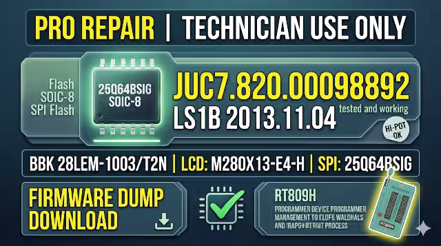
JUC7.820.00098892 Firmware Dump
BBK 28LEM-1003/T2N
Firmware Overview
This repository entry provides the complete SPI flash binary dump extracted from the JUC7.820.00098892 main board used in the BBK 28LEM-1003/T2N LED television. The dump targets the 25Q64BSIG memory IC and has been read, written, verified, and field-tested on a live unit using the RT809H universal programmer. Use this file to recover bricked, corrupted, or non-booting sets.
Hardware Specifications
| Brand | BBK |
| Model | 28LEM-1003/T2N |
| Main Board | JUC7.820.00098892 |
| LCD Panel | M280X13-E4-H |
| Resolution | 720p HD — 1366 × 768 |
| SPI Flash IC | 25Q64BSIG (64 Mbit / 8 MB) |
| Package | SOP-8 |
| Programmer | RT809H Universal Programmer |
| File Format | .bin (Raw Binary Dump) |
| Firmware Status | Tested 100 % Working |
SPI Flash Chip Identification
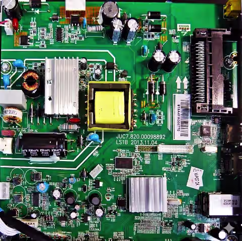
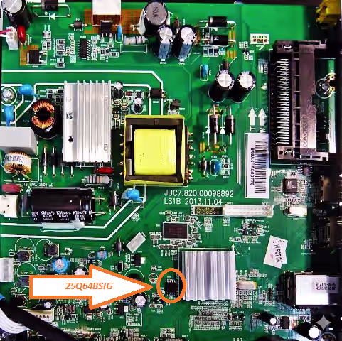
The 25Q64BSIG is located near the main SoC on the board. Match the orientation dot (pin 1) before clipping or desoldering. Use the reference image below.
Reported Fault Symptoms (This Model)
The following failures are commonly resolved by reflashing the SPI memory with a known-good dump:
- Stuck on BBK logo — infinite boot loop, never reaches home screen
- Dead set — no standby LED, no relay click, board draws minimal current
- Backlight illuminates but no picture and no OSD overlay
- Standby LED blinks in a pattern — protection mode lock-out
- Firmware OTA update interrupted — unit bricked mid-write
- HDMI / AV / USB ports not detected by the system
- Audio present but black screen — T-CON init data corrupted in flash
- OSD menu garbled, freezes, or shows incorrect language
- Continuous auto-restart cycle — powers on then immediately shuts down
- IR remote completely unresponsive — receiver config data lost
Diagnostic & Repair Protocol
- Board Verification: Confirm the silk-screen reads JUC7.820.00098892. Do not proceed if the board number differs — firmware is board-specific.
- Visual Inspection: Check for burnt resistors, swollen capacitors, cracked solder joints, or lifted pads around the power section and SPI chip.
- Power Rail Test: Measure standby 5 V, main 12 V, and logic 3.3 V with a DMM. All rails must be within ±5 % tolerance before programming.
- Desolder / Clip SPI: Use a hot-air station (320–350 °C, medium flow) to remove the 25Q64BSIG, or connect an SOP-8 test clip for in-circuit reading.
- Backup Original: Read the existing flash content via RT809H and save as
backup_original.bin. Verify chip ID: Winbond W25Q64BV. - Erase & Blank Check: Full chip erase → blank check must pass (all bytes 0xFF) before writing.
- Write Firmware: Load the downloaded
.binfile. Program the chip. Expected file size: 8,388,608 bytes (8 MB). - Verify: Run the Verify function in RT809H software. Result must be 0 errors / 100 % match.
- Resolder & Inspect: Reball or resolder the chip. Inspect all 8 pins under magnification for bridges, cold joints, or flux residue.
- Functional Test: Reconnect PSU, panel ribbon, and speakers. Power on — confirm logo → home screen → picture → sound → all inputs. Run factory reset from service menu if required.
Video Guide
Step-by-step walk-through covering chip removal, RT809H configuration, and firmware flashing for this board.
Download Firmware Dump
JUC7.820.00098892 — BBK 28LEM-1003/T2N — 25Q64BSIG — 8 MB BIN
A sponsor page will open first. Then click the same button again to access the direct download link.