Firmware Overview
This page provides a tested and verified SPI firmware dump for the TCL LED55B3710 television equipped with the 40-MS1306-MAB2LG main board. The binary file has been extracted directly from a fully operational unit and is ready to be programmed onto a replacement or corrupted 25Q32 SPI flash memory chip using the RT809H universal programmer.
This firmware dump restores the complete software stack including bootloader, main application, channel data defaults, panel timing configuration for the LVF550CSOT E1 V5 panel, and factory calibration values. It is the definitive solution when standard USB update methods fail due to deep memory corruption.
This resource is intended for professional TV repair technicians only. Incorrect flashing procedures may result in permanent board damage. Ensure you have proper equipment, ESD protection, and technical knowledge before proceeding.
Board Specifications
| Brand | TCL |
| TV Model | LED55B3710 |
| Screen Size | 55 Inch LED |
| Main Board | 40-MS1306-MAB2LG |
| Panel | LVF550CSOT E1 V5 |
| SPI Flash IC | 25Q32 (W25Q32 – 4MB / 32Mbit) |
| Programmer | RT809H Universal Programmer |
| File Type | BIN (Binary Dump) |
| File Size | 4 MB (4,194,304 bytes) |
| Firmware Status | Tested 100% Working |
| Dump Method | Direct SPI read via RT809H |
Known Issues for TCL LED55B3710
The following problems are commonly reported with the TCL LED55B3710 using the 40-MS1306-MAB2LG main board. This firmware dump addresses all software and memory-related failures listed below:
- Stuck on TCL Logo: TV powers on, displays the TCL boot logo, and freezes indefinitely without progressing to the home screen. Caused by corrupted bootloader or main application sector in SPI memory.
- Boot Loop / Repeated Restart: TV continuously restarts in a cycle – shows logo, turns off, powers back on. Indicates corrupted firmware checksum or damaged boot flag in flash memory.
- Black Screen with Backlight: Backlight LEDs illuminate but no picture or OSD appears. Typically caused by corrupted panel timing data or T-CON initialization values stored in the SPI flash.
- No Power Response (Standby LED Only): TV remains in standby with red LED on but does not respond to power button or remote. Main processor fails to boot due to completely erased or dead SPI chip.
- Software Update Failure: USB firmware update process fails, freezes, or shows error codes. Original SPI data is too corrupted for the built-in update routine to execute properly.
- No Audio Output: Picture displays normally but audio is absent from all sources. Corrupted audio codec initialization parameters within the firmware image.
- HDMI / AV Ports Not Detected: Connected devices are not recognized on any input. Source switching module data within the SPI firmware is damaged.
- Menu Freeze / OSD Corruption: On-screen display shows garbled text, settings menu freezes, or user interface elements display incorrectly.
- EEPROM Data Corruption: Factory settings lost, random channel sorting, incorrect region settings, or distorted color calibration after power surge or unstable supply.
Diagnostic and Repair Protocol
Follow this systematic procedure to diagnose the fault and successfully flash the firmware dump onto the 40-MS1306-MAB2LG main board:
Phase 1: Initial Diagnosis
Phase 2: Firmware Flashing Procedure
Phase 3: Reassembly and Testing
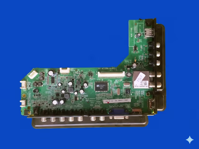
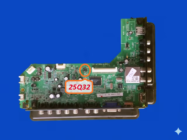
SPI Flash Memory Location
The image below shows the exact location of the 25Q32 SPI flash memory chip on the 40-MS1306-MAB2LG main board. This is the target IC that must be desoldered, programmed with the firmware dump file using the RT809H, and resoldered to complete the repair.
Video Tutorial
Watch the complete firmware flashing procedure for the 40-MS1306-MAB2LG board. This tutorial covers chip identification, desoldering technique, RT809H programmer setup, and verification steps:
Download Firmware Dump
40-MS1306-MAB2LG SPI BIN file for TCL LED55B3710
For professional technician use only. Verify board number matches before flashing.
Frequently Asked Questions
What SPI chip is used on the 40-MS1306-MAB2LG board?
The main board uses a 25Q32 (Winbond W25Q32 or compatible) SPI NOR flash memory chip. It is an 8-pin SOIC package with 4MB (32 megabit) storage capacity. This chip stores the complete firmware including bootloader, operating system, and calibration data.
Which programmer is required to flash this firmware?
The RT809H universal programmer is the recommended tool for this procedure. It provides reliable SPI flash read, erase, write, and verify operations for the 25Q32 chip. A SOP8 to DIP8 adapter socket or SOP8 test clip cable is required to interface the chip with the programmer.
What issues does this firmware dump resolve?
This firmware resolves all software and memory-related failures including: stuck on logo, no boot, black screen with active backlight, repeated restart loops, corrupted EEPROM data, OSD corruption, failed USB updates, missing audio, unresponsive HDMI ports, and complete NAND/SPI memory failure on the TCL LED55B3710.
Can I use a clip to flash without desoldering?
In-circuit programming using a SOP8 test clip is possible in some cases, but it is not recommended for this board. The main processor and other components sharing the SPI bus can interfere with the programming signals, causing write failures or data corruption. Desoldering the chip ensures a clean, reliable flash operation.
The TV still does not work after flashing. What should I check?
If the TV does not boot after successful programming and verification, check: (1) SPI chip solder joints for cold joints or bridges, (2) correct chip orientation on the PCB, (3) LVDS cable connection to the panel, (4) main board power rail voltages, and (5) whether the main processor IC itself is damaged. A hardware-level fault on the board may exist alongside the firmware corruption.