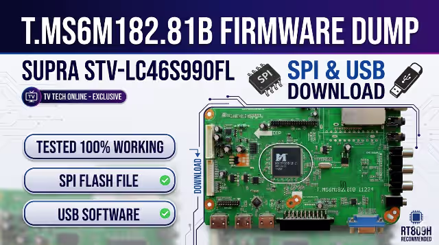
T.MS6M182.81B Firmware Dump
SUPRA STV-LC46S990FL
Board Overview
This page provides the verified T.MS6M182.81B firmware dump for the SUPRA STV-LC46S990FL LCD television. The firmware is available as an SPI flash dump for programmer-based repair and as a USB update package for menu-based installation. Both files have been extracted, tested, and confirmed 100% functional by our technician team.
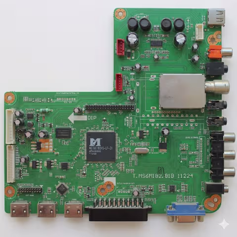
T.MS6M182.81B Main Board – SUPRA STV-LC46S990FL
Firmware Specifications
| Parameter | Details |
|---|---|
| Board Model | T.MS6M182.81B |
| TV Model | SUPRA STV-LC46S990FL |
| Screen Size | 46 Inch LCD |
| Chipset | MStar MS6M182 |
| Firmware Type | SPI Flash Dump / USB Update |
| SPI Firmware File | bin_6m182.bin |
| Programmer | RT809H |
| Flash IC Type | 25Q64 / 25Q128 (8MB–16MB) |
| Status | Tested – 100% Working |
SPI Flash IC Location
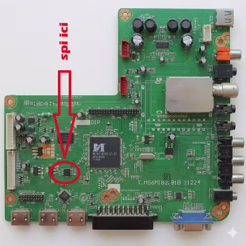
SPI Flash IC Location – T.MS6M182.81B Board
The SPI flash memory IC is located near the main processor. Use the RT809H universal programmer to read, erase, and write the firmware dump. Ensure the IC is properly seated in the programmer socket or use an in-circuit SOP8 clip for on-board programming.
SPI Programmer Method (RT809H)
- Power off the TV and disconnect from mains supply completely.
- Locate the SPI flash IC on the T.MS6M182.81B board (refer to image above).
- Connect the RT809H programmer via SOP8 clip or desolder the IC.
- Open RT809H software, detect the flash IC model (25Q64/25Q128).
- Erase the chip completely before writing new data.
- Load the firmware file bin_6m182.bin and write to the IC.
- Verify the written data against the source file to confirm integrity.
- Reinstall the IC (if desoldered) and power on the TV for testing.
USB Firmware Update Instructions
- Format the USB flash storage device to FAT32 file system.
- Place the firmware file “bin_6m182.bin” at the root of the USB drive (not inside any folder).
- Connect the USB flash storage device to the TV’s USB connector.
- Power on the TV and access the user menu using the remote control.
- Navigate to and select the “Update via USB” function.
Video Tutorial
Watch the complete firmware installation walkthrough for the T.MS6M182.81B board:
Diagnostic & Repair Protocol
Common Issues Resolved by This Firmware
- TV stuck on logo screen or boot loop – firmware corruption in SPI flash
- No picture, sound only – corrupted panel configuration or T-CON initialization data
- TV turns on then immediately shuts off – watchdog reset due to corrupted boot sector
- No signal on all input sources (HDMI, AV, TV) – input matrix configuration lost
- Remote control not responding – IR protocol data corrupted in EEPROM section
- Channel search finds no channels – tuner initialization parameters missing
- Distorted or scrambled OSD menu – font and graphics data corruption in flash
- USB port not detecting devices – USB driver firmware block damaged
- Audio output failure on all sources – audio DAC initialization data error
- Backlight turns on but no image, no OSD – main firmware execution failure
- TV powers on to standby (red LED) and will not start – secondary bootloader failure
- HDMI handshake failure with external devices – HDCP key or EDID data corruption
Pre-Repair Checklist
| Check Item | Action Required |
|---|---|
| Power Supply Voltages | Verify 5V, 12V, 24V rails are within ±5% tolerance |
| SPI Flash IC | Test with programmer – confirm IC is readable before writing |
| EEPROM (24C32/24C64) | Reset or replace if panel settings are corrupted |
| Crystal Oscillator | Confirm 24MHz oscillation on main IC |
| LVDS Cable | Inspect for broken pins or oxidation at connector |
| Electrolytic Capacitors | Check for bulging or leaking caps near power section |
Download Firmware
Click the button once to proceed through verification, then click again to access the direct download link.