 FIRMWARE DUMP
TESTED 100%
FIRMWARE DUMP
TESTED 100%
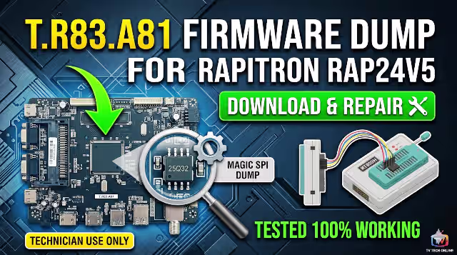
T.R83.A81 Firmware Dump for RAPITRON RAP24V5 – SPI 25Q32 Memory Repair Download
This technical resource provides the verified SPI firmware dump for the T.R83.A81 main board used in the RAPITRON RAP24V5 television. If your unit is experiencing memory corruption, boot failure, or stuck-on-logo symptoms, this dump file will restore full functionality when programmed onto the 25Q32 SPI flash chip using an RT809H universal programmer. This firmware has been tested and confirmed 100% working on production hardware.
Firmware Specifications
| Brand | RAPITRON |
|---|---|
| Model | RAP24V5 |
| Main Board | T.R83.A81 |
| Panel | PT236AT01-1-XC-1 |
| SPI Flash IC | 25Q32 (32Mbit / 4MB) |
| Programmer | RT809H Universal Programmer |
| File Type | Full SPI Dump (.bin) |
| Status | TESTED 100% WORKING |
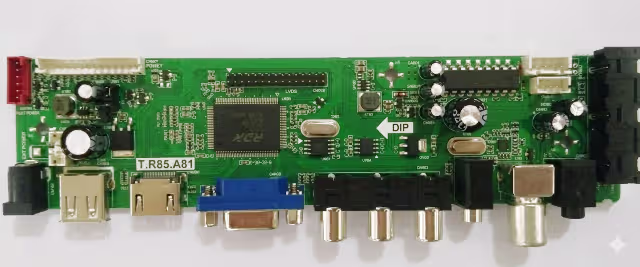
Main Board Reference
T.R83.A81 Main Board – RAPITRON RAP24V5 (component side view)
SPI Flash IC Location
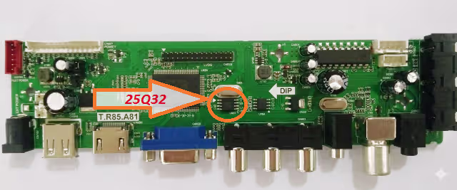
25Q32 SPI Flash IC – Target chip for firmware programming via RT809H
Known Issues – RAPITRON RAP24V5
Common Failures Resolved by This Firmware Dump
- Stuck on boot logo – TV powers on but freezes at the RAPITRON splash screen and never reaches the home menu
- Completely dead unit (no standby LED) – Power supply confirmed good, main board unresponsive due to corrupted boot sector in SPI memory
- Black screen with backlight – Backlight illuminates normally but no OSD, no picture, and no audio output
- Boot loop / auto-restart cycle – TV repeatedly turns on and off in an endless reboot cycle
- No signal on all input sources – AV, HDMI, and USB inputs all display “No Signal” despite functional connected devices
- Audio present without video – Sound plays normally through speakers but screen remains completely dark
- Corrupted OSD or garbled menu – On-screen display shows scrambled text, missing icons, or incorrect language data
- Dead after power surge or lightning – SPI flash data corrupted following electrical surge event
- EEPROM data corruption – Service menu settings lost, channel data erased, or factory reset fails to execute
Diagnostic and Repair Protocol
Step-by-Step SPI Firmware Programming Procedure
1
Safety First – Disconnect Power: Unplug the TV from mains power. Discharge residual capacitor voltage by pressing the power button for 10 seconds. Wear an ESD wrist strap connected to a grounded surface before handling the PCB.
2
Access the Main Board: Remove the back panel screws and carefully detach all ribbon cables and connectors. Locate the T.R83.A81 main board and identify the 25Q32 SPI flash chip (8-pin SOIC package, typically near the main processor).
3
Connect the RT809H Programmer: Attach the SOIC8 test clip directly to the 25Q32 chip. Ensure pin 1 orientation is correct (dot marking on IC aligns with pin 1 on clip). For best results, desolder the chip and place it in the ZIF socket adapter.
4
Read and Backup Original Data: Launch the RT809H software, select IC model W25Q32 / GD25Q32, and perform a full read. Save this backup file with a descriptive name in case you need to revert.
5
Erase the SPI Chip: Execute a full chip erase command. Verify the erase was successful by performing a blank check – all bytes should read
0xFF.6
Write the Firmware Dump: Load the downloaded T.R83.A81 firmware dump file into the programmer software. Click Write/Program and wait for the process to complete without interruption. Do not disconnect during writing.
7
Verify the Write: After writing completes, perform a Verify operation to compare the written data against the source file. The verification must show 0 errors (100% match).
8
Reassemble and Test: Resolder the chip (if desoldered) or remove the clip. Reconnect all cables and ribbon connectors. Power on the TV and confirm: boot logo appears, OSD menu is accessible, all inputs function, audio and video output correctly.
Video Tutorial
Download T.R83.A81 Firmware Dump
SPI 25Q32 Full Dump File – RAPITRON RAP24V5 – Verified and Tested
File will be available after verification step
Frequently Asked Questions
What issues does the T.R83.A81 firmware dump fix for RAPITRON RAP24V5?
This firmware dump resolves stuck on logo, no boot, black screen with backlight, dead after power surge, corrupted EEPROM data, no signal on all inputs, boot loop, and audio without video issues. It restores the SPI 25Q32 flash memory to factory-verified state.
Which programmer is required to flash the SPI 25Q32 on T.R83.A81?
The RT809H universal programmer is required. Connect to the 25Q32 SPI flash chip using a SOIC8 test clip for in-circuit programming, or desolder the chip and use the ZIF socket adapter for the most reliable results.
Is this T.R83.A81 firmware tested and working?
Yes, this firmware dump has been tested 100% working on the RAPITRON RAP24V5 with panel PT236AT01-1-XC-1. It was read from a known-good working unit and verified for data integrity before distribution.
Can I use this dump on a different panel or TV model?
This dump is specifically calibrated for the PT236AT01-1-XC-1 panel. Using it with a different panel may cause display issues including incorrect resolution, inverted colors, or no picture. Always match the exact board revision and panel model.