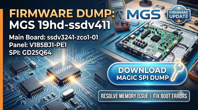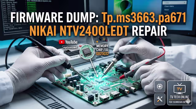
Tp.ms3663.pa671 Firmware Dump for Nikai Ntv2400ledt – SPI Flash GD25Q32 Download
Overview
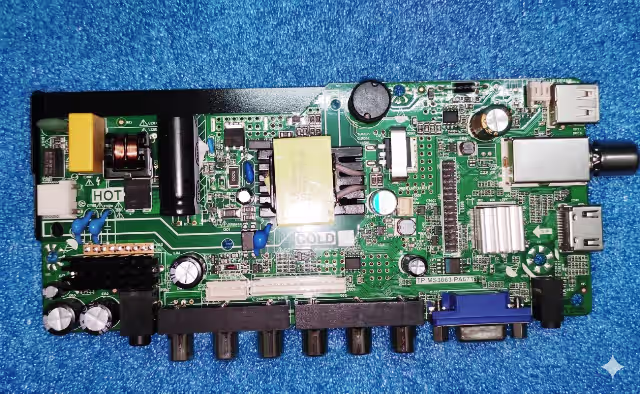
This page provides a verified SPI memory dump for the Nikai Ntv2400ledt television equipped with the Tp.ms3663.pa671 main board. The firmware binary targets the GD25Q32 flash IC and is intended exclusively for professional TV repair technicians performing memory-level diagnostics and restoration.
If your Nikai Ntv2400ledt is experiencing a dead state after power surge, boot loop, frozen logo, no display output, or backlight-only condition, reflashing this dump via the RT809H universal programmer will restore full system functionality.
Hardware Specifications
| Brand | Nikai |
|---|---|
| Model | Ntv2400ledt |
| Main Board | Tp.ms3663.pa671 |
| Panel | HV236WHB-N40 |
| SPI Flash IC | GD25Q32 (32Mbit / 4MB) |
| Programmer | RT809H |
| File Type | BIN (Full Memory Dump) |
| Firmware Status | Tested 100% Working |
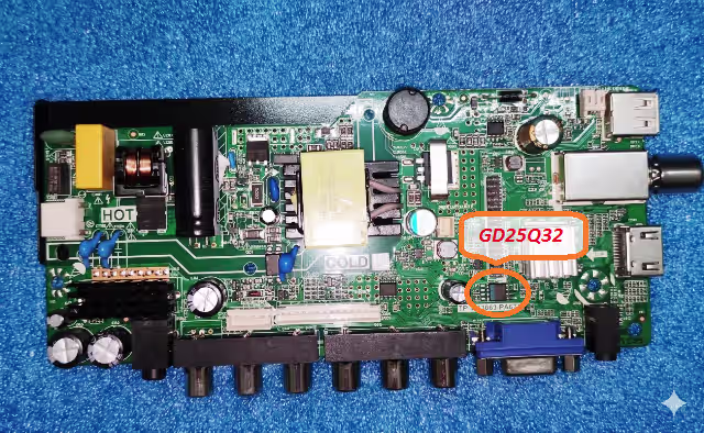
SPI Flash IC Location
The image below highlights the GD25Q32 SPI flash IC position on the Tp.ms3663.pa671 PCB. Desolder or use an in-circuit clip (SOP8) when reading or writing with the RT809H programmer.
Common Issues with Nikai Ntv2400ledt (Tp.ms3663.pa671)
The following symptoms indicate corrupted or damaged SPI flash firmware requiring a memory dump reprogramming:
- Dead set after power surge – TV does not respond to power button or remote; standby LED is off or blinks once
- Boot loop or stuck on logo – Unit repeatedly restarts or remains frozen at the Nikai splash screen
- Backlight on, no picture or OSD – Panel illuminates but no image, menu, or on-screen display appears
- No signal on all inputs – All source inputs (HDMI, AV, USB) display “No Signal” even with connected devices
- Sound but no display – Audio plays normally; screen remains dark with backlight active
- Software corruption after failed update – Unit becomes non-functional after interrupted USB firmware upgrade
- EEPROM data error – Unstable channel storage, volume resets, or settings fail to save after power off
- Abnormal shutdown or auto-restart – TV turns off randomly or enters a reboot cycle during operation
Diagnostic and Repair Protocol
Follow this structured workflow before and during the SPI reflash procedure to ensure safe and successful repair:
Step 1 – Visual Inspection
Inspect the Tp.ms3663.pa671 board for burnt components, swollen capacitors, cracked solder joints, or damaged traces around the power regulation area and SPI IC.
Step 2 – Power Supply Verification
Confirm that the power supply delivers correct voltages: 5V standby, 12V main, and 3.3V logic rail. Use a multimeter to verify stability under load.
Step 3 – SPI Flash IC Assessment
- Power off and disconnect the TV from mains supply completely
- Locate the GD25Q32 SPI flash IC on the PCB (refer to the image above)
- Connect the RT809H programmer using an SOP8 test clip or desolder the IC
- Read the existing firmware and save a backup copy of the original bin file
- Verify the backup file integrity by reading twice and comparing checksums
Step 4 – Firmware Programming
- Open RT809H software and select the IC model: GD25Q32
- Erase the chip completely before writing
- Load the downloaded Tp.ms3663.pa671 firmware bin file
- Write the firmware to the SPI flash IC
- Verify the write operation – ensure no mismatch errors
Step 5 – Post-Flash Verification
- Resolder the IC (if desoldered) with proper flux and temperature control
- Reconnect the panel flex cable and all harnesses
- Power on the TV and observe boot sequence
- Access the service menu to confirm panel resolution matches HV236WHB-N40
- Test all inputs (HDMI, USB, AV), audio output, and remote control response
Video Tutorial – SPI Flash Programming Guide
Watch the complete step-by-step tutorial for programming the GD25Q32 SPI flash on the Tp.ms3663.pa671 main board:
Download Tp.ms3663.pa671 Firmware Dump
File: Nikai Ntv2400ledt – GD25Q32 – Full SPI BIN
Click the button above. A sponsor page opens first, then your download link activates.
Related Firmware Downloads
Frequently Asked Questions
What SPI flash IC is used on the Tp.ms3663.pa671 board for Nikai Ntv2400ledt?
The SPI flash memory IC is GD25Q32 (32Mbit / 4MB). It stores the main firmware, channel data, and system configuration for the Tp.ms3663.pa671 main board.
Which programmer is recommended for this firmware dump?
The RT809H universal programmer is recommended. It provides reliable read, write, and verify support for the GD25Q32 SPI flash IC. Use an SOP8 clip for in-circuit programming or desolder the chip for best results.
Is this firmware dump tested and working?
Yes. This SPI dump has been tested on the Nikai Ntv2400ledt with the Tp.ms3663.pa671 main board and HV236WHB-N40 panel. It is confirmed 100% working with all functions operational.
Can I use this dump on a different panel other than HV236WHB-N40?
No. This firmware is configured specifically for the HV236WHB-N40 panel. Using it with a different panel model may result in no display, incorrect resolution, or panel damage. Always match the panel model exactly.
What should I do if the TV still does not work after flashing?
If the TV remains non-functional after a verified successful flash, inspect the power supply voltages, check the T-CON board, verify the LVDS cable connection to the panel, and test backlight driver circuitry. The issue may be hardware-related rather than firmware corruption.